
Graft element, system and method for joining plant stem sections using such graft element, and system and method for preparing such graft element

Inactive Publication Date: 2014-02-27
IG SPECIALS
View PDF28 Cites 3 Cited by
  • Summary
  • Abstract
  • Description
  • Claims
  • Application Information

AI Technical Summary

Benefits of technology

The invention provides an alternative procedure for grafting that addresses the problems of the prior art. It introduces a graft element that is easy to apply, supports the graft, and can be removed relatively easily. The graft element is made of a resilient material and takes the form of a tubular structure with a hollow center and side openings. The use of a resilient material allows the graft to adjust its form to the stems it encloses. The side opening allows excess liquid to escape and prevents rotting of the stems. The cylinder has a circular cross-section that can be applied to many types of plants. The width of the side opening close to the inner surface of the cylinder is smaller than the width near the outer surface of the graft element. The graft element can be gripped and cut using a strand of material. The supporting surface ensures effective clamping during the cutting process. The technical effects of this invention include simplifying the grafting process, providing better support for the graft, and improving the quality of the grafting process.

Problems solved by technology

The process of grafting is generally labor intensive.
However, such pegs are relatively heavy for small plants, in particular non-woody plants, and each peg is relatively expensive.
Furthermore, the overall success rate is low, which leads to considerable wastage of plants, labor and space.
Nevertheless, individual placement of such clips by hand remains time consuming and can encourage the spread of plant diseases.
Although the sleeve appears to be an improvement over the use of a clothes peg, its manufacture and deployment are relatively complex.

Method used


Image

  • Graft element, system and method for joining plant stem sections using such graft element, and system and method for preparing such graft element
  • Graft element, system and method for joining plant stem sections using such graft element, and system and method for preparing such graft element
  • Graft element, system and method for joining plant stem sections using such graft element, and system and method for preparing such graft element

Examples


Embodiment Construction

[0043]The following is a description of various embodiments of the invention, given by way of example only and with reference to the drawings.

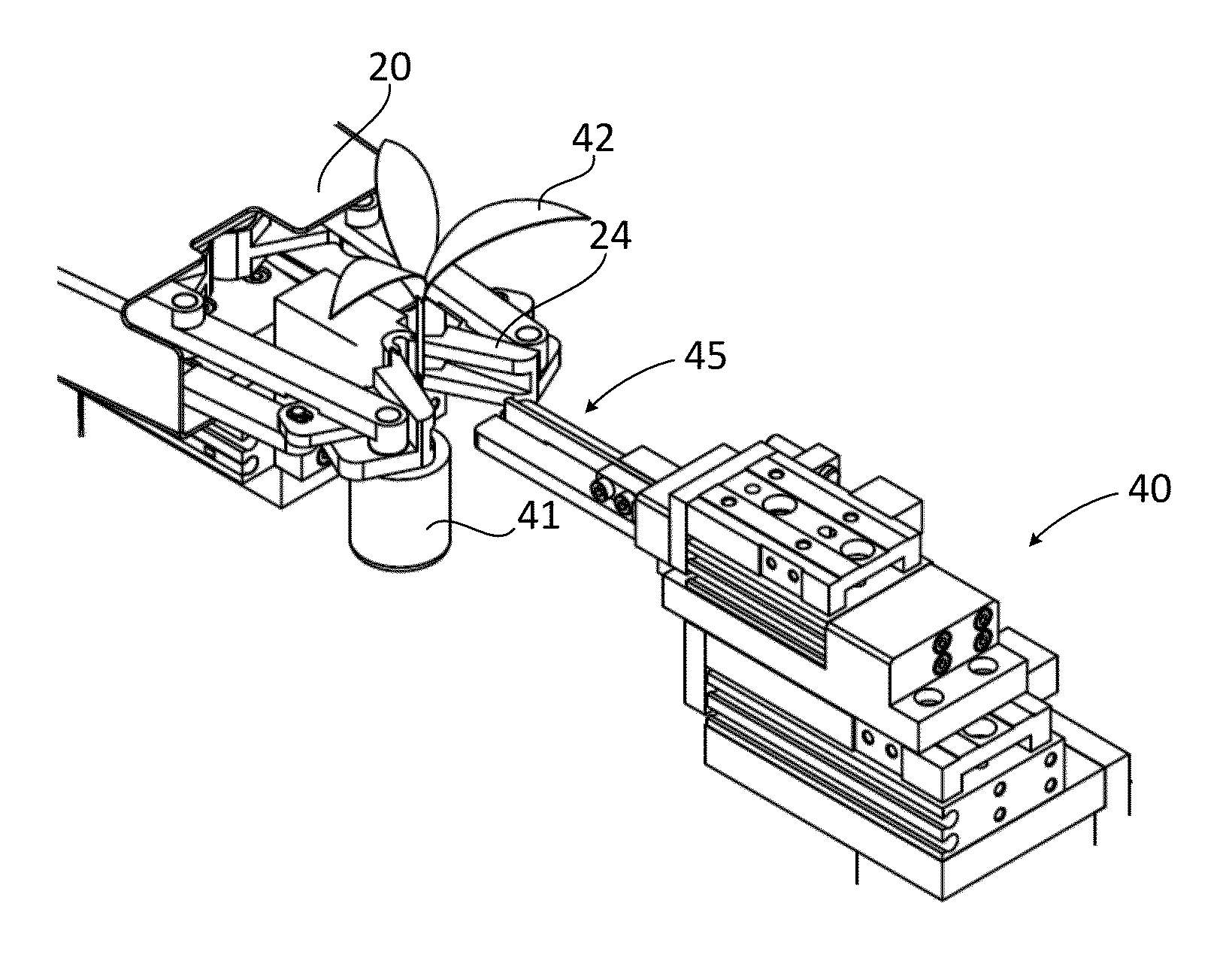
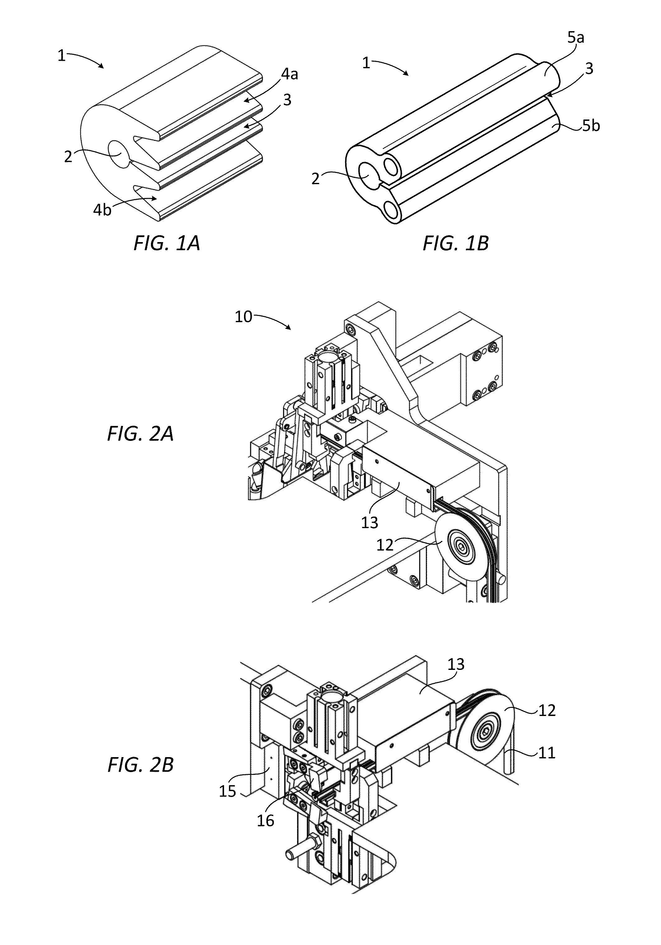
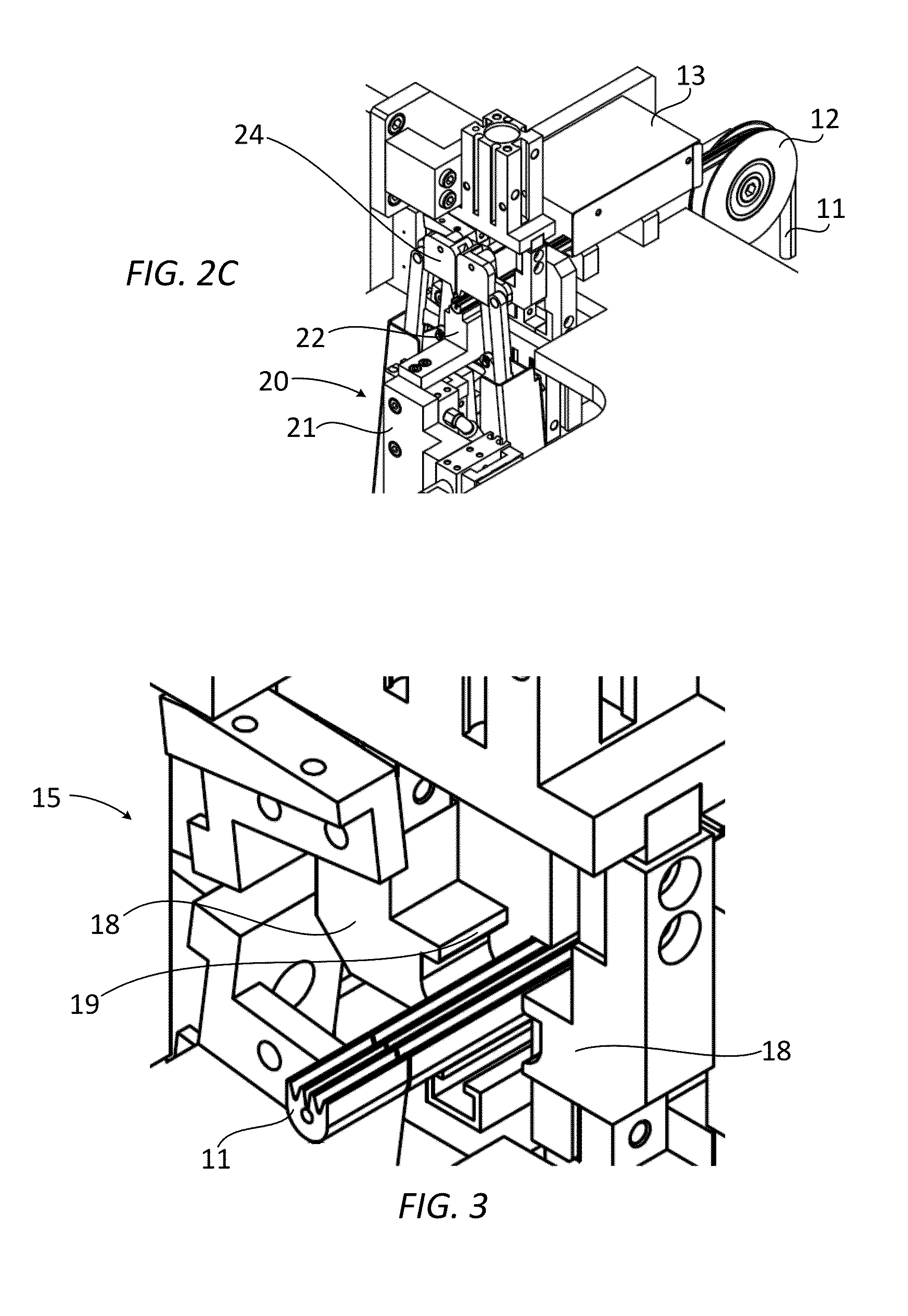
[0044]FIGS. 1A, 1B both schematically show a graft element 1 according to an embodiment of the invention. The graft element 1 is made of a resilient material, for example an elastomeric material such as silicone. More examples of suitable materials include, but are not limited to, low-density polyethylene (LDPE), a thermoplastic elastomer (TPE) and a liquid silicone rubber (LSR). Preferably, the length of the graft element is such that it provides sufficient support at the excess of as little material as possible. A typical length of the graft element 1 is about 6-16 mm, preferably about 8-14 mm, more preferably about 10-12 mm. For example, for tomato plants a size of 12 mm turns out to provide good results.

[0045]The graft element 1 takes the form of a tubular structure having a hollow center that extends in a longitudinal direction of the gra...


PUM

PropertyMeasurementUnit
Angleaaaaaaaaaa
Angleaaaaaaaaaa
Forceaaaaaaaaaa

Abstract

The present invention relates to a graft element for joining together plant stem sections. The graft element is made of a resilient material and takes the form of a tubular structure having a hollow center that extends in a longitudinal direction so as to form a cylinder. The graft element further comprises a side opening along its length and two elongated members. The side opening is connected to the hollow center over the entire length of the graft element. The two elongated members are located at opposite sides of the side opening and oriented substantially parallel thereto. The elongated members are provided with cutouts for receiving a gripping unit. The invention further relates to systems and methods for joining plant stem sections using the graft element. Finally, the invention relates to a system and a method for preparing the graft element.

Description

CROSS REFERENCE TO RELATED APPLICATIONS[0001]This application is a continuation of PCT application number PCT / EP2012 / 051067 filed on 24 Jan. 2012, which claims priority from Netherlands application number NL 1038539 filed on 24 Jan. 2011. All applications are hereby incorporated by reference in their entireties.BACKGROUND OF THE INVENTION[0002]1. Field of the Invention[0003]The invention relates to a graft element for joining together plant stem sections. The invention further relates to a system and a method for preparing such graft element. Finally, the invention relates to a system and a method for joining together plant stem sections, preferably by means of such graft element.[0004]2. Description of the Related Art[0005]It is well known in the fields of horticulture and fruit that a plant section of a preferred species of plant may be transplanted onto a section of a hardier species. The plant will then grow, having the qualities of the preferred species while enjoying benefits ...

Claims


Application Information

Patent Timeline
IPC IPC(8): A01G1/06B26D7/02
CPCB26D7/02A01G1/06Y10T83/04Y10T83/7573A01G2/32A01G2/38A01G2/35
Inventor STRUIJK, WIMVAN DER EL, WIMDE KONING, DIRK JANSCHOUTEN, WILLEM NICOLAAS
Owner IG SPECIALS
Learn More