Electric machine

Inactive Publication Date: 2014-02-27
BOMBARDIER TRANSPORTATION GMBH
View PDF7 Cites 4 Cited by
  • Summary
  • Abstract
  • Description
  • Claims
  • Application Information

AI Technical Summary

Benefits of technology

[0012]According to another embodiment of the invention said connections of said second channels are substantially uniformly distributed over the extension of the respective first channel, which promotes efficient cooling of the entire rotor as long as it rotates.
[0013]According to another embodiment of the invention said first channels extend substantially axially through the rotor body with respect to said axis of rotation of the rotor. One of the advantages of such an extension of the first channels is that this makes it normally easier to ensure that the presence of these channels will not have a noticeable influence upon the magnetic flux inside the rotor than would the extension be otherwise. Furthermore, the flow rate inside the channels may be kept on a high level when the channels have a straight extension.
[0014]According to another embodiment of the invention the rotor has a plurality of poles defined by said permanent magnets and disposed in the rotor body around said axis of rotation, and said first channels extend with respect to a cross-section of the rotor body through rotor body portions separating two adjacent rotor poles. This results in a minimum of disturbance of the magnetic flux inside the rotor

Problems solved by technology

However, fouling and contamination may occur as a result of dust, especially metal dust reaching the rotor and sticking thereto as a consequence of the presence of the permanent magnets, which is the reason for the presence of said sealing means in an electric machine of the type defined in the introduction.
However, this forced cooling may fail and the power to the electric machine wi

Method used


Image

  • Electric machine
  • Electric machine
  • Electric machine

Examples


Example

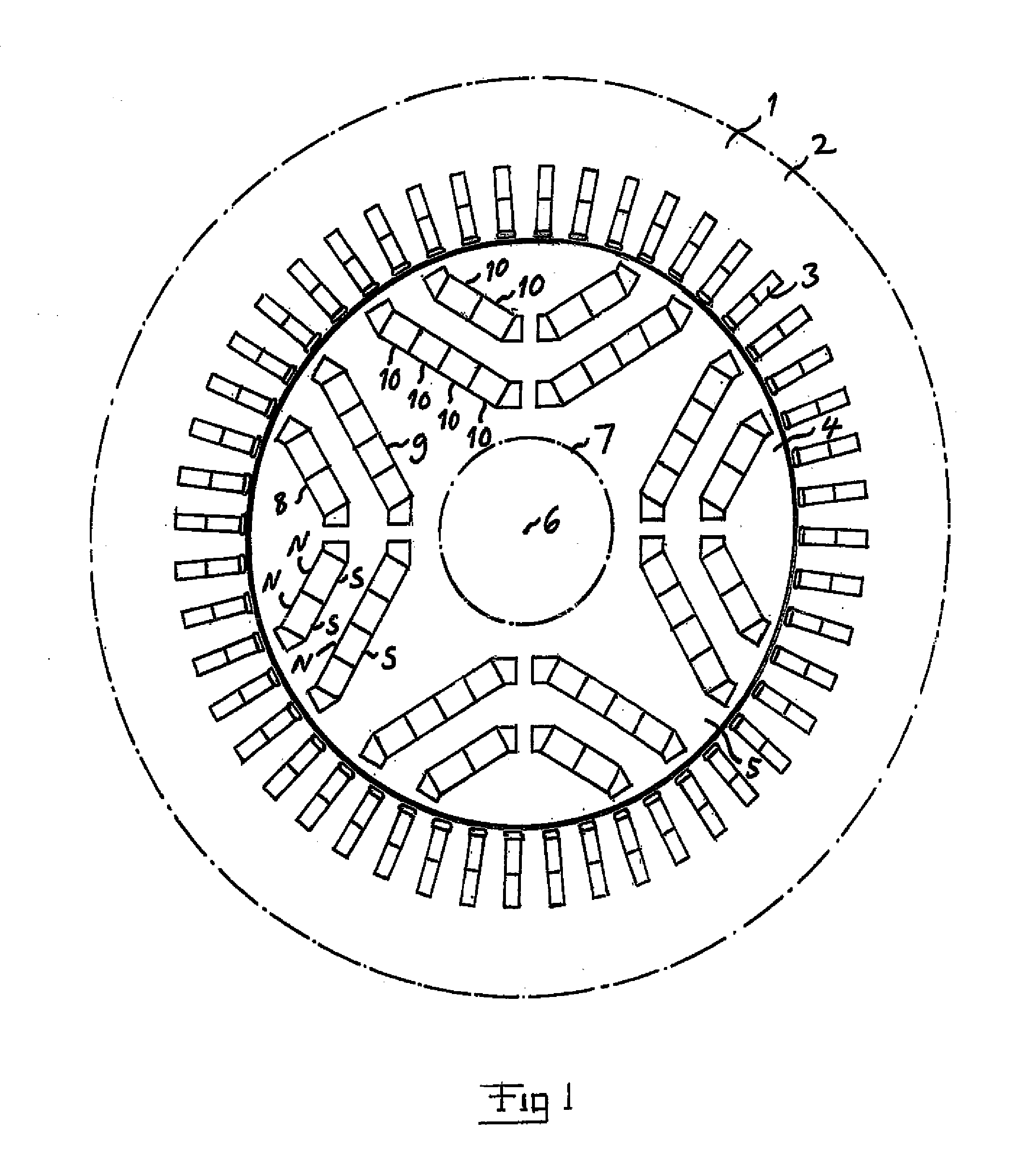
[0031]FIG. 1 shows schematically in an axial end view some of the main parts of a track-bound vehicle electric machine of the type to which the present invention relates and which is disclosed more in detail in EP 2 264 860. This electric machine has a stator 1 with a stator body 2 with a stator winding (not shown) wound therearound and configured to electrically create a plurality of stator poles disposed around the inner periphery of the stator body. Said stator winding is received in radial slots 3 in the stator body, extending over the entire length of this body. 48 slots are in this way uniformly distributed around the inner periphery of the stator body 2, so that 12 said slots belong to one stator pole in the case of a four-pole electric machine as in the embodiment shown in FIG. 1. The total number of slots and number of slots per pole may of course be any other conceivable.

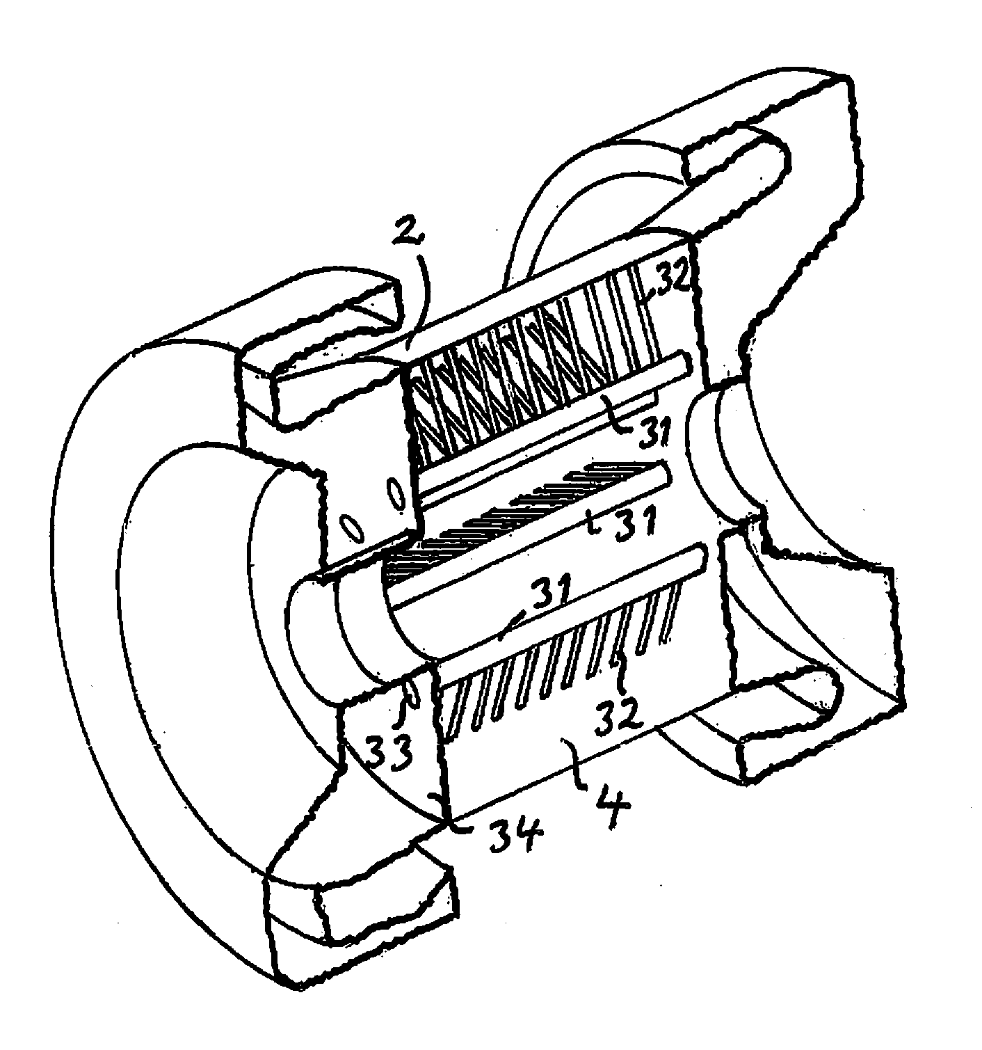
[0032]The electric machine further comprises a rotor 4 with a rotor body 5, which as the stator body is...


PUM


Abstract

An electric machine with a rotor (4) rotatably disposed within a stator (2) has a plurality of permanent magnets received in the rotor body of the rotor. Rotor body plates are stacked so as to form at least two first channels (31) extending inside the rotor body from one axial end of the rotor to an opposite axial end thereof and having an opening (33) to the exterior of the rotor body in an end surface of the latter at at least one of these axial ends, and at least one separate second channel (32) associated with each first channel and connecting the respective first channel to a space circumferentially surrounding the rotor and separating the rotor and the stator by opening at the periphery of the rotor body so as to upon rotation of the rotor throw air out from said second channel to said space for cooling the rotor body.

Description

TECHNICAL FIELD OF THE INVENTION AND BACKGROUND ART[0001]The present invention relates to an electric machine comprising a stator having a stator body with a stator winding wound therearound and configured to electrically create a plurality of stator poles disposed around the inner periphery of the stator body, means configured to connect said stator winding to an AC source or receiver, a rotor rotatably disposed within said stator and having a rotor body comprising a laminated assembly of mutually electrically insulated annular plates axially stacked with respect to an axis of rotation of the rotor, said rotor body having a plurality of permanent magnets received therein, and means sealing the rotor and a space circumferentially surrounding the rotor and separating the rotor and the stator for preventing air flow from the surroundings of the machine from reaching the rotor and said space.[0002]Such an electric machine may operate as motor and / or generator, although this disclosure ...

Claims


Application Information

Patent Timeline
IPC IPC(8): H02K9/06
CPCH02K9/06H02K1/2766H02K1/32H02K5/128
Inventor NORDLUND, ERIKJAGERS, THERESESIMA, MIKAEL
Owner BOMBARDIER TRANSPORTATION GMBH
Why Eureka
Try Eureka