Mechanical and Electrical-Integrated Drive Unit

a drive unit and mechanical technology, applied in the direction of machines/engines, rotary/oscillating piston pump components, liquid fuel engines, etc., can solve the problems of low flexibility of electronic components mounted on the control circuit board, easy heat generation in the control circuit chamber, etc., to improve the flexibility of electronic components layout and reduce heat generation.

Inactive Publication Date: 2014-02-27
HITACHI AUTOMOTIVE SYST LTD
View PDF7 Cites 31 Cited by
  • Summary
  • Abstract
  • Description
  • Claims
  • Application Information

AI Technical Summary

Benefits of technology

[0007]It is an object of the present invention to provide a mechanical and electrical-integrated drive unit that is configured to electrically connect a motor coil with a control circuit board and that can improve the flexibility of layout of electronic components mounted on the control circuit board while minimizing influences of heat generated by a motor and of a contaminant on the control circuit chamber.
[0009]The aspect of the present invention can minimize an influence of the heat generation of the motor or of a contaminant on a control circuit board chamber and improve the flexibility of layout of electronic components mounted on the control circuit board.

Problems solved by technology

Accordingly, since the opening exists between the motor chamber and the control circuit chamber, the control circuit chamber is easily subjected to heat generated by the motor portion.
Further, if a contaminant occurs inside the motor chamber, or if operating fluid leaks into the motor chamber, it can reach the control circuit chamber.
Therefore, there is a problem about low flexibility of layout of electronic components mounted on the control circuit board.

Method used


Image

  • Mechanical and Electrical-Integrated Drive Unit
  • Mechanical and Electrical-Integrated Drive Unit
  • Mechanical and Electrical-Integrated Drive Unit

Examples


embodiment 1

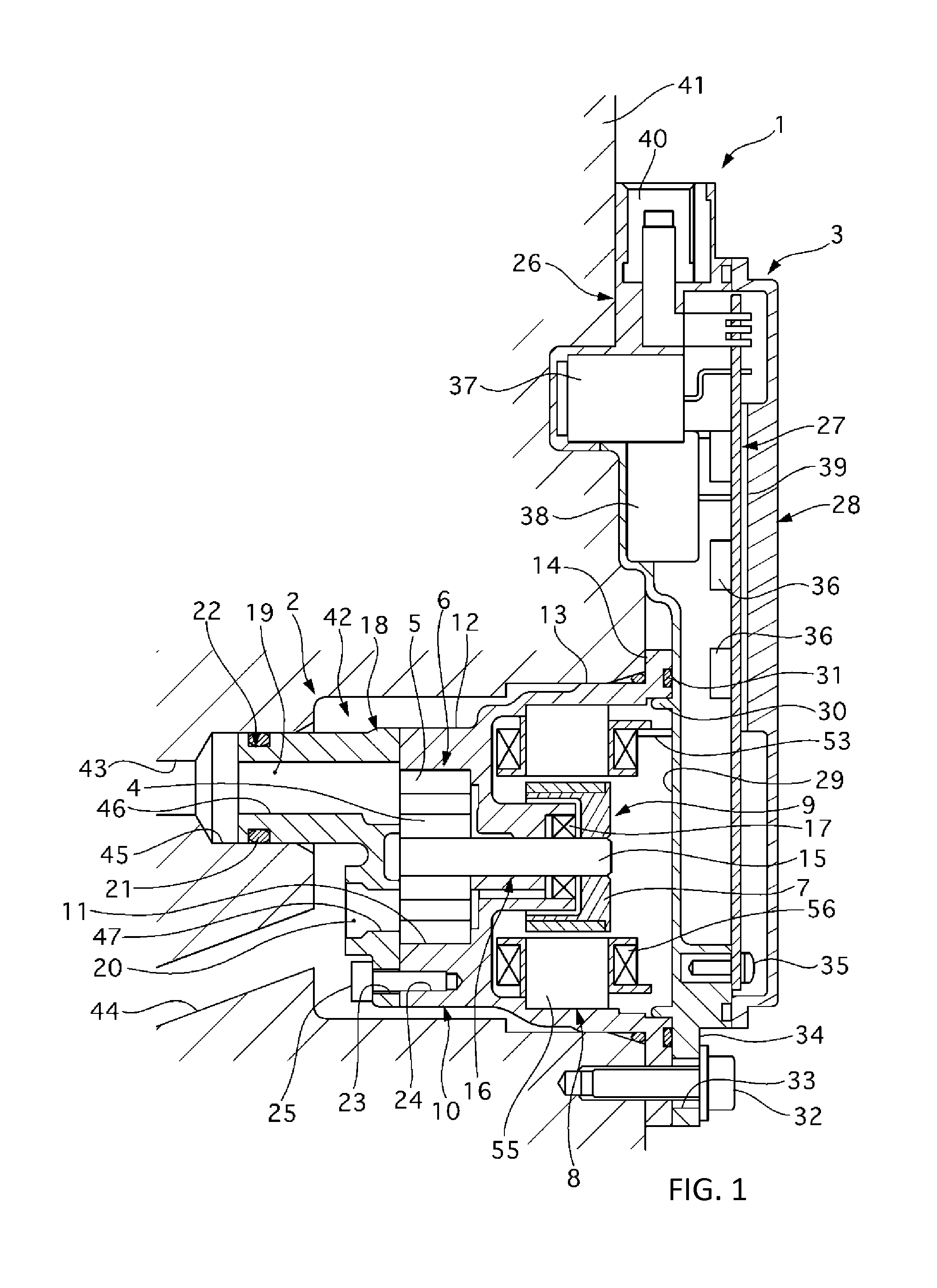
[0018]FIG. 1 is a longitudinal cross-sectional view of an electric oil pump (a mechanical and electrical-integrated drive unit 1) according to a first embodiment.

[0019]The electric oil pump 1 of the first embodiment is a pump mounted for an automatic transmission for a vehicle equipped with a function to stop an engine when the vehicle is stopped. The automatic transmission separately has a main (mechanical) pump driven by the rotative power from the engine or a motor. When the engine is stopped, however, also the mechanical pump is not operative and therefore hydraulic pressure cannot be produced. Further, if the hydraulic pressure lowers due to a cause inside the automatic transmission, time is taken until the hydraulic pressure necessary for re-start is ensured, leading to degraded drive performance in some cases. Therefore, the electric oil pump 1 which can deliver hydraulic pressure regardless of the operating conditions of the engine is installed separately from the main pump....


PUM


Abstract

A mechanical and electrical-integrated drive unit is provided that is configured to be able to protect a control circuit board from thermal stress, a contaminant, or operating fluid from a motor housing chamber and that can improve the flexibility of layout of electronic components mounted on the control circuit board. The drive unit includes a motor, a control circuit board for controlling energization of the motor, the circuit board installed integrally with the motor, an obstruction portion isolating the motor from the circuit board, and an inverter housing for the circuit board. A coil wire of the motor is covered at its end by a conductive thin-walled narrow tube so as to be joined to the tube. The tube is fixedly inserted into a through-hole formed in the obstruction portion so that at least the leading end portion of the tube is projected into the inverter housing.

Description

BACKGROUND OF THE INVENTION[0001]1. Field of the Invention[0002]The present invention relates to a mechanical and electrical-integrated drive unit.[0003]2. Description of the Related Art[0004]In the conventional technology disclosed in JP-2005-229658-A, the coil wire of the motor housed in the motor chamber is arranged to extend to the housing provided with the control circuit chamber housing the control circuit board therein. In addition, the coil wire is joined to the connecting terminal which is previously secured to the housing. Thus, the coil wire is electrically connected to the control circuit board.SUMMARY OF THE INVENTION[0005]The conventional technology described above has the structure in which the terminal formed on the motor is projected into the control circuit chamber. Accordingly, since the opening exists between the motor chamber and the control circuit chamber, the control circuit chamber is easily subjected to heat generated by the motor portion. Further, if a con...

Claims


Application Information

Patent Timeline
Patent Type & Authority Applications(United States)
IPC IPC(8): H02K11/00
CPCH02K11/0073F04C2/18F04C11/008F04C15/008F04C2240/803F04C2240/808H02K11/33
Inventor HYODO, MINORU
Owner HITACHI AUTOMOTIVE SYST LTD
Why Eureka
Try Eureka