Projection Laser Profiler

a laser profiler and projection technology, applied in the direction of instruments, reference lines/planes/sectors, optical elements, etc., can solve the problems of time-consuming and inaccurate data surveys, inability to accurately measure the rotational aspect of adjacent lasers, and inability to accurately measure the interior of pipelines, etc., to eliminate the alignment problem of laser diodes, accurate data surveys, and uniform width

Active Publication Date: 2014-02-27
JENNISON
View PDF10 Cites 7 Cited by
  • Summary
  • Abstract
  • Description
  • Claims
  • Application Information

AI Technical Summary

Benefits of technology

[0009]An object of the present invention is to provide a laser profiler that utilizes a single diode, thereby eliminating the need for a plurality of redundant laser diodes. An additional object of the present invention is to eliminate alignment issues with the laser diodes by providing a single laser diode. In addition, it is an object of the present invention to provide a laser profiler that produces a crisp ring of light having a uniform width such that accurate data surveys and reliable information can be obtained.

Problems solved by technology

These line thickness inconsistencies result in inaccurate data surveys and unreliable information.
Furthermore, the alignment of the rotational aspect of adjacent lasers is a time consuming task in order to yield a clean ring of light.

Method used


Image

  • Projection Laser Profiler
  • Projection Laser Profiler
  • Projection Laser Profiler

Examples


Embodiment Construction

[0025]For purposes of the description hereinafter, the terms “upper”, “lower”, “right”, “left”, “vertical”, “horizontal”, “top”, “bottom”, “lateral”, “longitudinal”, and derivatives thereof shall relate to the invention as it is oriented in the drawing figures. However, it is to be understood that the invention may assume various alternative variations, except where expressly specified to the contrary. It is also to be understood that the specific devices illustrated in the attached drawings, and described in the following specification are simply exemplary embodiments of the invention. Hence, specific dimensions and other physical characteristics related to the embodiments disclosed herein are not to be considered as limiting.

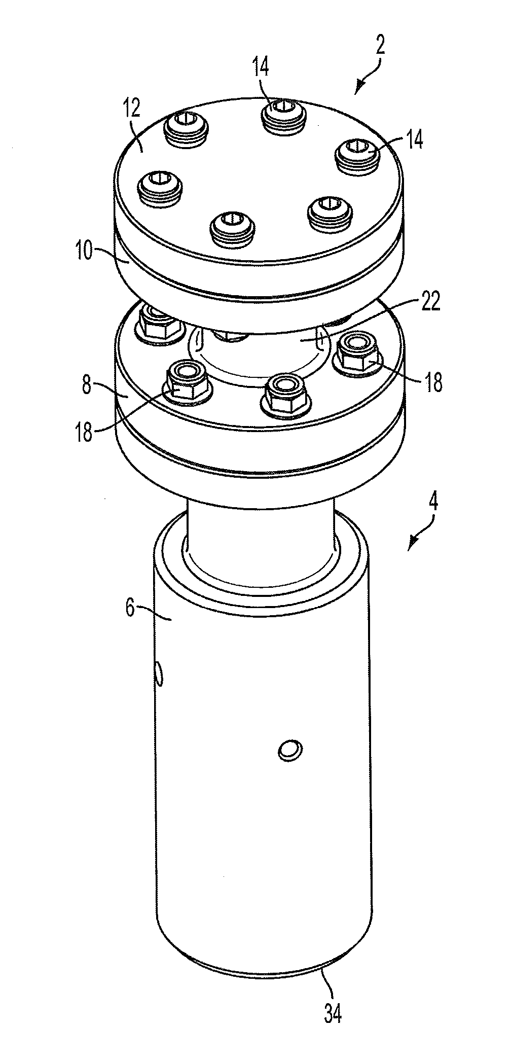
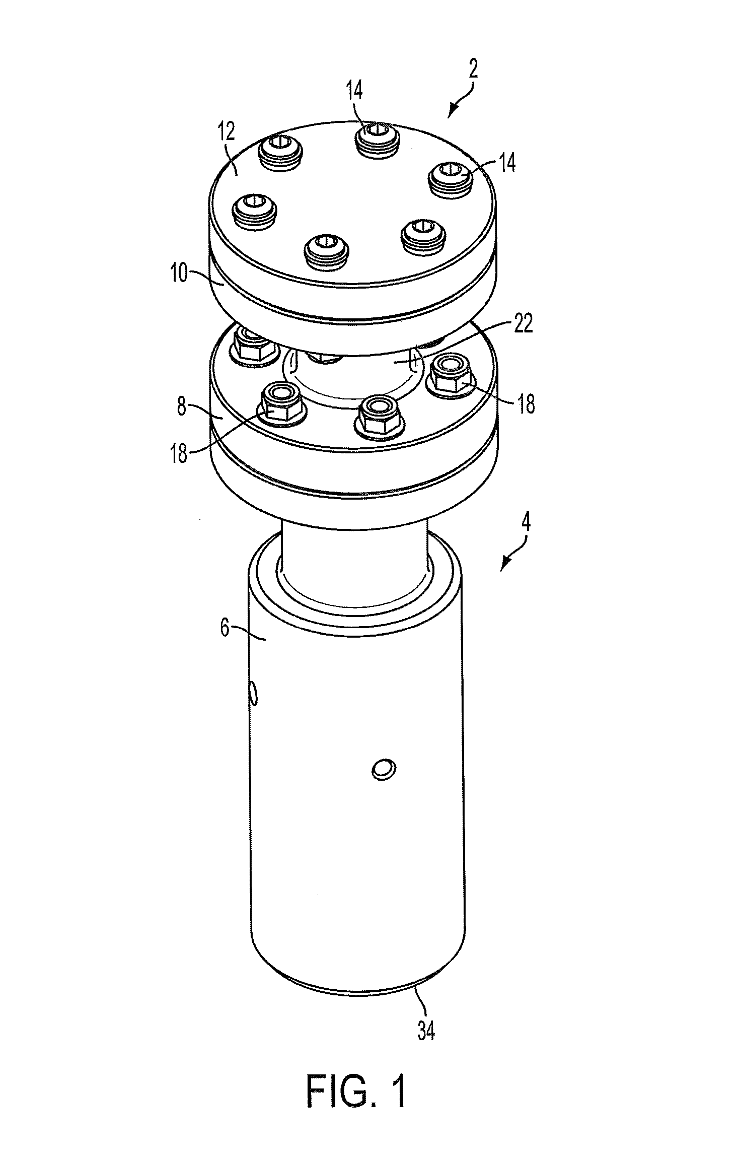
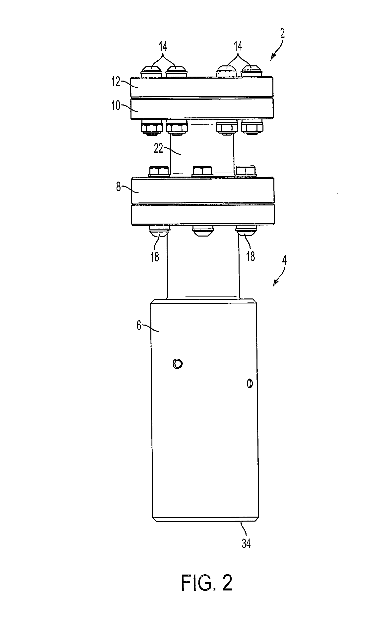
[0026]With reference to FIGS. 1-4, a laser profiler, generally denoted as reference numeral 2, includes a generally cylindrical housing, generally denoted as reference numeral 4, having a base 6, a first flange portion 8 connected to the base 6, and a second f...


PUM

PropertyMeasurementUnit
diameteraaaaaaaaaa
transparentaaaaaaaaaa
widthaaaaaaaaaa

Abstract

A laser profiler includes: a laser diode mounted within a substantially cylindrical housing; a conical mirror positioned upstream from the laser diode within the cylindrical housing; and a transparent shroud positioned to surround the conical mirror. A beam produced by the laser diode is directed to the conical mirror and is reflected therefrom at 360° through the transparent shroud to produce a ring of light.

Description

CROSS REFERENCE TO RELATED APPLICATIONS[0001]This application claims the benefit of U.S. Provisional Patent Application No. 61 / 692,877 entitled “Projection Laser Profiler” filed Aug. 24, 2012, which is hereby incorporated by reference in its entirety.BACKGROUND OF THE INVENTION[0002]1. Field of the Invention[0003]The present invention, in general, is directed to a system and method for profiling the interior of a pipeline and, more specifically, for a system and method for profiling the interior of a pipeline by projecting a 360° ring of laser light onto the interior of the pipeline.[0004]2. Description of Related Art[0005]Known systems for profiling or inspecting pipelines typically comprise a television camera or a video camera mounted on a self-propelled electric tractor or on a sled pushed by a semi-rigid cable along the pipe from an open end of the pipe. Lights are attached to illuminate the pipeline interior. Both the lights and the camera are powered by the cable. An image of...

Claims


Application Information

Patent Timeline
Patent Type & Authority Applications(United States)
IPC IPC(8): G01N21/88G01N21/954
CPCG01N21/954G01N21/8806E03F7/12G01C15/004
Inventor JOHNSEN, MARK P.COOPER, THEODORE J.
Owner JENNISON
Why Eureka
Try Eureka