Electronic protection device, method for operating an electronic protection device, and use thereof

a protection device and electronic technology, applied in the direction of emergency protection arrangement details, electrical apparatus, arrangements responsive to excess voltage, etc., can solve the problems of premature aging, long life long lifetime of existing safety fuse, so as to prolong the lifetime or delay the aging of the protection device of the invention, the effect of extending the lifetime or delay of the protection devi

Active Publication Date: 2014-02-27
DSPACE DIGITAL SIGNAL PROCESSING & CONTROL ENG
View PDF1 Cites 10 Cited by
  • Summary
  • Abstract
  • Description
  • Claims
  • Application Information

AI Technical Summary

Benefits of technology

[0020]An advantage of the invention is that the electronic protection device of the invention, if the protection function is used, has a longer lifetime or delayed aging in comparison with a protection device that has only a fuse element. Particularly if the two aforementioned protection devices being compared prevent an excessive increase of the first current by means of the respective associated protection method over a period of days, weeks, or months, the lifetime of the protection device of the invention is extended the more considerably compared with a “mere” fuse element approach, the more often the protection method is tripped, therefore the more frequently an overcurrent needs to be interrupted by the protection device.
[0021]Another advantage of the invention is, particularly, a higher reliability of the protection device and/or improved protection from the consequential damages of an overload of the protection device, for example, improved protection from a fire hazard, which can result from a worn out or defective protection device.
[0022]The advantage of the increased reliability of the protection device of the invention in comparison with long-known protection devices also comes into play particularly when another external voltage source (not shown in the figures) is wrongly connected at the output of the protection device; this can lead to a “feedback” of a current via the fuse element

Problems solved by technology

Such a fuse block, like the majority of safety fuses used today, has the disadvantage that after a fault event, therefore after the melting of the so-called fuse element, the existing safety fuse must be replaced by a new safety fuse.
A disadvantage of a fuse element of the indicated type is that during its use a possible overloading of an electrical circuit can in fact be prevented for a calculable time period, but during relatively frequent or continuous operation of a fuse element in the “tripped state”, therefore in the substantially current-blocking state, due to a “continuous load” on the fuse element irreversible changes occur in the fuse element, which considerably shorten its lifetime.
In other words, for example, the described continuous load on the fuse element leads to its premature aging, which depending on the occurrence of other boundary conditions can lead to the destruction of the fuse element, for example, under unfavorable boundary conditions even after a few days.
In cases in which, for example, a wiring error remains undetected for a longer period of time, for example, for a time interval of a number of days, weeks, or months, this can have serious consequences, for example, when the component connected to the fuse element is connected to a voltage source or a reference potential in such a way that the fuse element in the aforementioned time interval (days, weeks, or months) is kept substantially continuously in the “tripped,” therefore blocking state.
The destruction of the fuse element, possibly occurring after this type of continuous load, can subsequently bring about a considerably increas

Method used


Image

  • Electronic protection device, method for operating an electronic protection device, and use thereof
  • Electronic protection device, method for operating an electronic protection device, and use thereof
  • Electronic protection device, method for operating an electronic protection device, and use thereof

Examples


Embodiment Construction

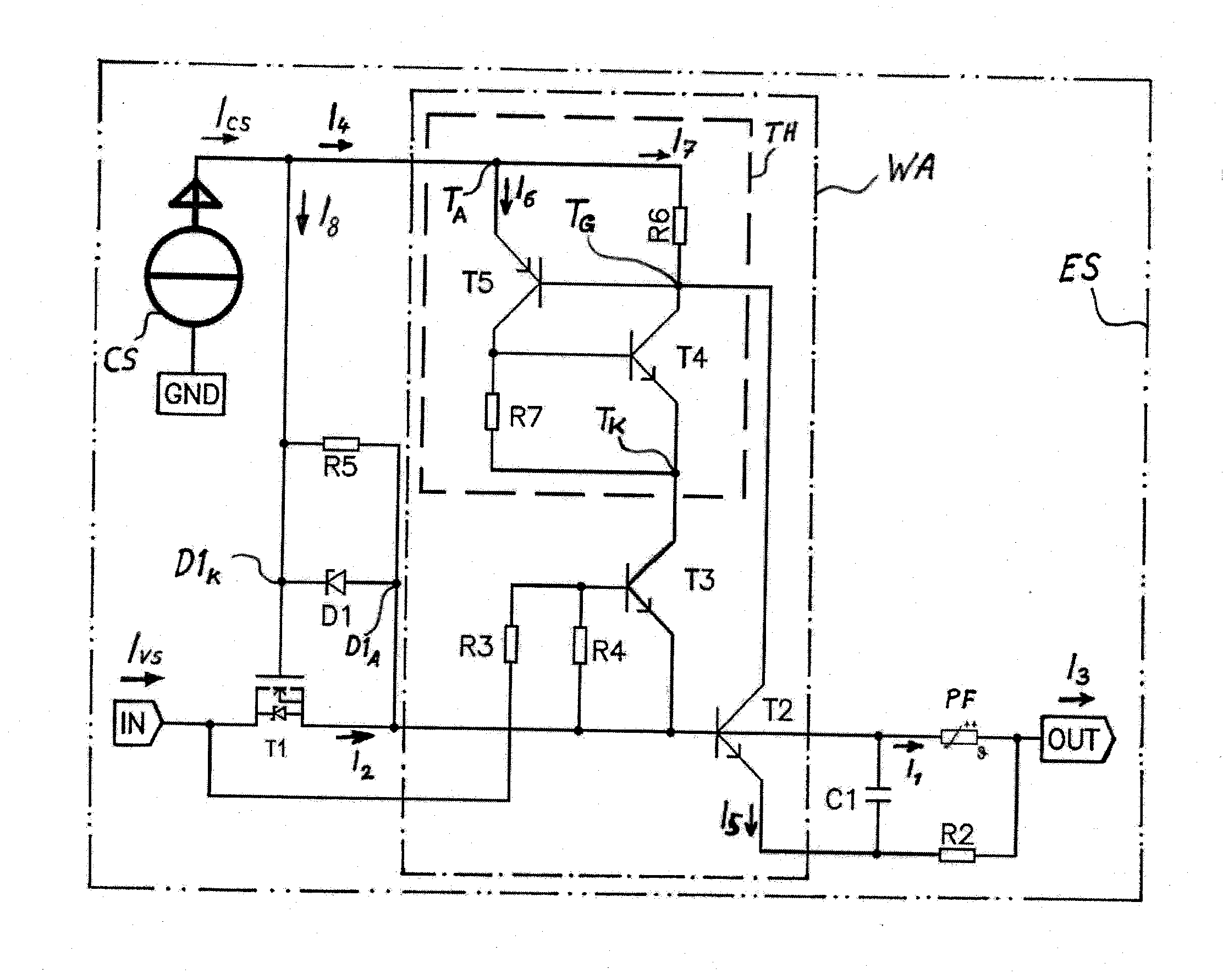
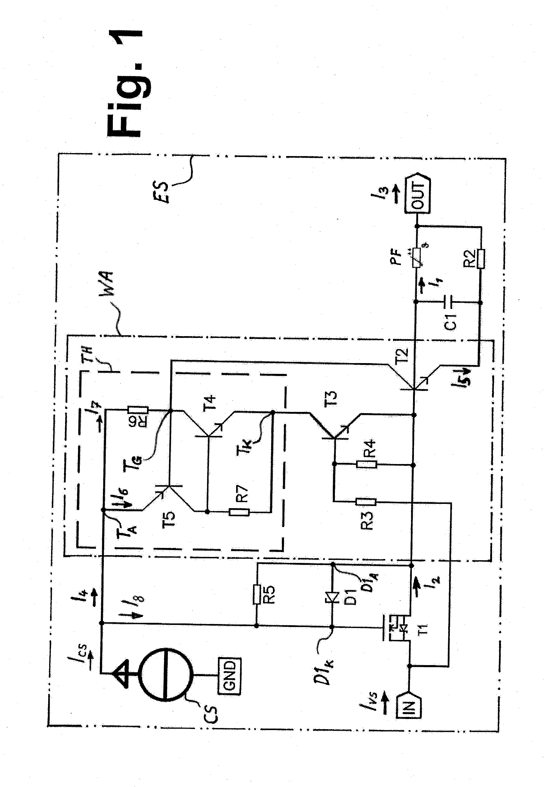
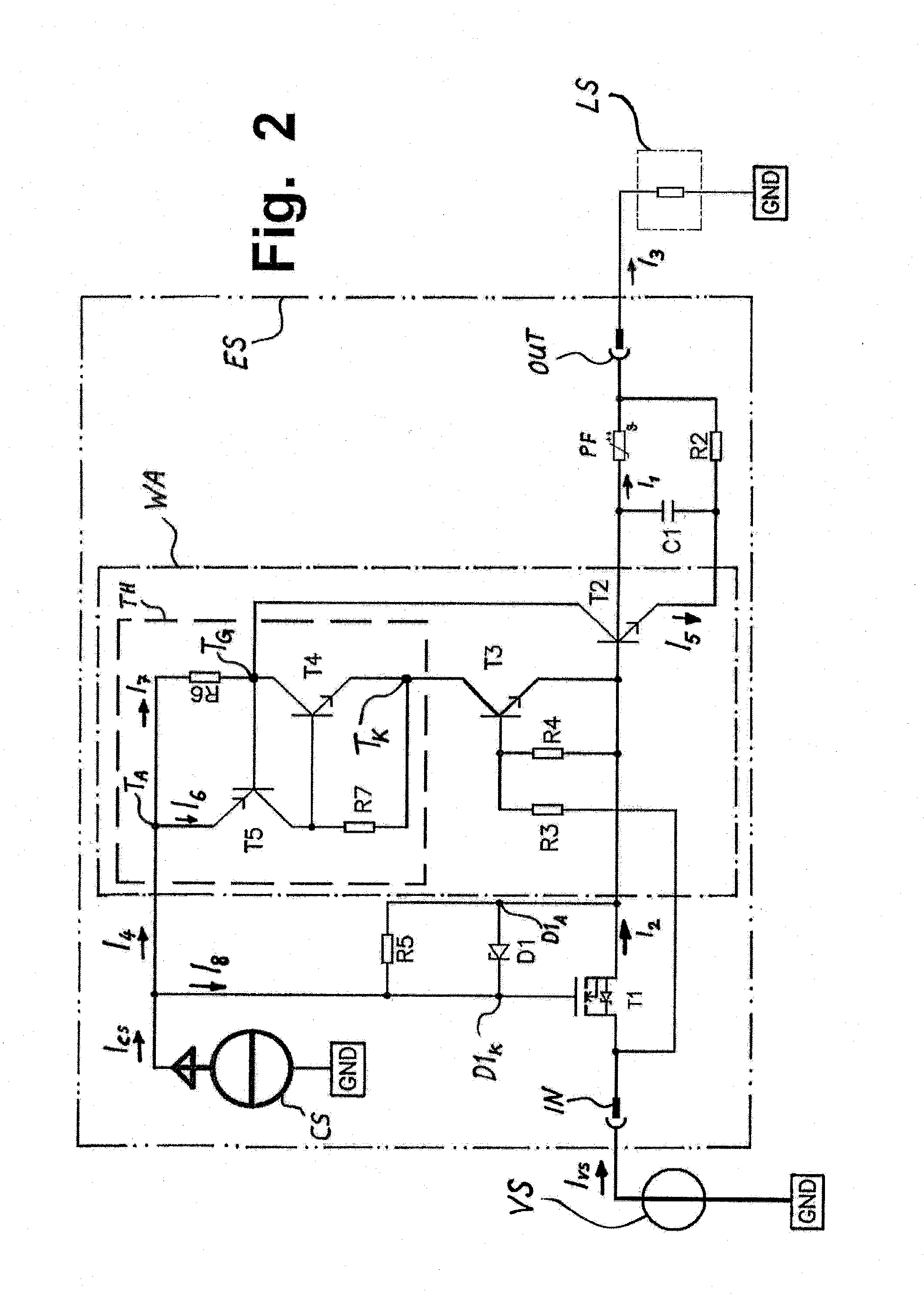
[0043]Exemplary embodiments of the electronic protection device according to the invention will be explained in greater detail in the following text with use of FIGS. 1 to 3. In addition, other advantages of the invention or advantages of the embodiments of the invention will be presented below with reference to the drawings. In this respect, similar parts are labeled with identical designations. The characteristic curves of FIG. 4, FIG. 5, and FIG. 6 are highly schematized; i.e., FIGS. 4, 5, and 6 are not measured characteristic curves but simplified characteristic curves, which make clear the mode of action and some of the advantages of the invention or the embodiments of the invention.

[0044]In the text below, the reference character “PF” is used for the fuse element, which is thermally resetting.

[0045]With the following examples and with the use of FIG. 2, FIG. 3, and FIG. 4, the two aforementioned action sequences, which were already mentioned in this description in the definiti...


PUM


Abstract

An electronic protection device for protecting at least one electrical load, connectable to the protection device, whereby the electronic protection device has an input terminal and an output terminal, and whereby the protection device includes a fuse element, which is thermally self-resetting, and whereby the fuse element is provided and set up to conduct or limit a first current as a function of a fuse element temperature, whereby a limiting component is provided to limit the first current, and whereby the limiting component has a first transistor that is connected in series to the fuse element and a monitoring circuit that influences the first transistor. The monitoring circuit blocks the first transistor when the first current reaches or exceeds a predefined maximum current value and unblocks it when the first current reaches or falls below a predefined reset current value.

Description

[0001]This nonprovisional application claims priority under 35 U.S.C. §119(a) to German Patent Application No. DE 10 2012 107 779.7, which was filed in Germany on Aug. 23, 2012, and which is herein incorporated by reference.BACKGROUND OF THE INVENTION[0002]1. Field of the Invention[0003]The present invention relates to an electronic protection device for protecting at least one electrical component connectable to the protection device. The invention relates further to a method for operating an electronic protection device and the use of an electronic protection.[0004]2. Description of the Background Art[0005]A number of protection devices whose purpose is to protect a voltage source and / or a load, connected to the voltage source, particularly from excessive currents are known from the state of the art.[0006]Such protection devices were developed and employed even at the beginning of the industrial use of electrical energy, as, for example, U.S. Pat. No. 438,305 of T. A. Edison for a...

Claims


Application Information

Patent Timeline
IPC IPC(8): H02H1/00
CPCH02H1/0007H02H3/08H02H9/025
Inventor GRUBER, PAUL
Owner DSPACE DIGITAL SIGNAL PROCESSING & CONTROL ENG
Why Eureka
Try Eureka