Suspension for high power micro speaker and high power micro speaker having the same

a high-power micro speaker and suspension structure technology, which is applied in the direction of transducer details, electrical transducers, electrical apparatus, etc., can solve the problems of reducing the sound pressure of the micro speaker, affecting the sound quality of the speaker, and generating unbalanced vibration, so as to prevent unbalanced vibration, reduce the intensity of vertical vibration, and facilitate low sound vibration

Active Publication Date: 2014-02-27
EM TECHNOLOGY CO LTD
View PDF6 Cites 27 Cited by
  • Summary
  • Abstract
  • Description
  • Claims
  • Application Information

AI Technical Summary

Benefits of technology

[0019]In the conductive suspension for high power provided by the present Invention, the land portions for use in soldering or welding the lead-in wires of the voice coil are disposed on the long connection portions positioned in a short direction, which prevents cracks from occurring in the conductive pattern in the event of high power vibration, and the land portions are symmetrically positioned, which prevents unbalanced vibration.
[0020]Moreover, in the conductive suspension provided by the present invention, some parts of the protective films on the long connection portions positioned in a short direction are removed to reduce the intensity of vertical vibration, which facilitates low sound vibration when the speaker is mounted.
[0021]Additionally, in the conductive suspension provided by the present invention, some part of the protective film on the central portion of the suspension is removed to improve a sound pressure.

Problems solved by technology

Therefore, unbalanced vibration is often generated due to the absence of the suspension, and the lead wire of the coil is often down in high power due to a tensile force, which makes it difficult for the micro speaker to be applied to high power.
In the case of the micro speaker using the suspension, an increase in weight of the diaphragm, which results from the use of the suspension, leads to a decrease in sound pressure of the micro speaker.
In addition, cracks may occur in the conductive pattern in high power, causing a defect.

Method used


Image

  • Suspension for high power micro speaker and high power micro speaker having the same
  • Suspension for high power micro speaker and high power micro speaker having the same
  • Suspension for high power micro speaker and high power micro speaker having the same

Examples


Embodiment Construction

[0030]Hereinafter, preferred embodiments of the present invention will be described in detail with reference to the accompanying drawings.

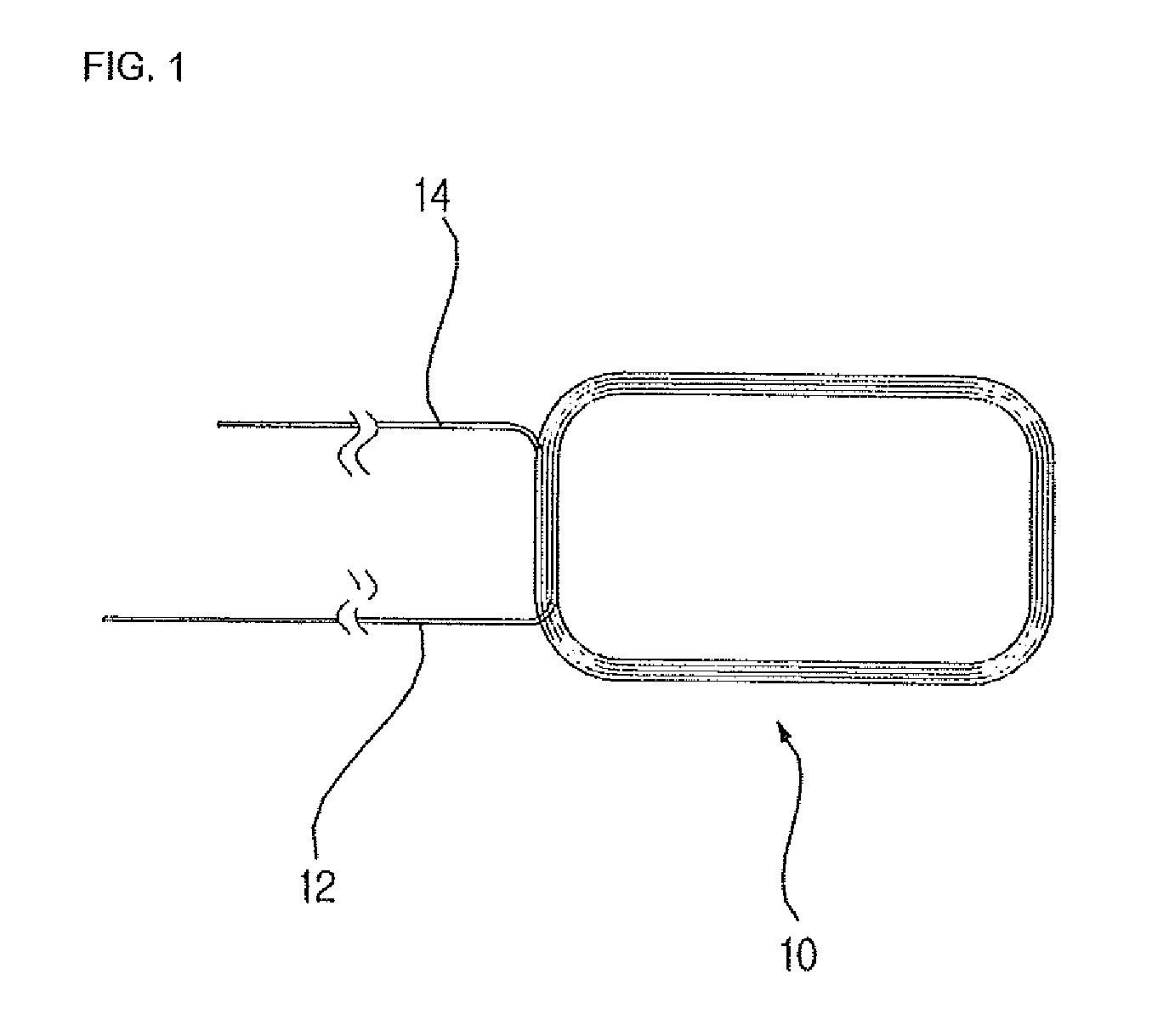
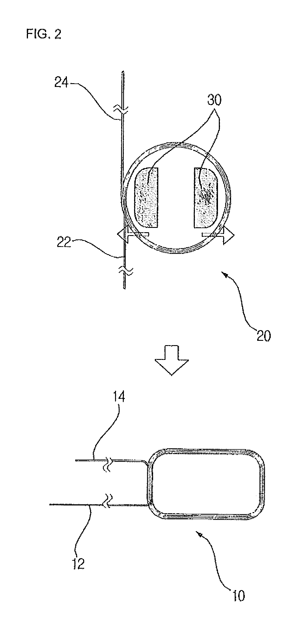
[0031]FIG. 5 is a view showing a voice coil lead-in wire structure provided in a high power micro speaker according to a first embodiment of the present invention. A voice coil 100 provided in the high power micro speaker according to the first embodiment of the present invention is formed in a rectangular shape like a conventional rectangular coil 10. However, the voice coil 100 provided in the high power micro speaker of the present invention and the voice coil 10 of the prior art have a difference in drawing-out directions of lead wires 120 and 140. The lead wires 120 and 140 of the voice coil 100 are not disposed on the same side of the rectangular shape side by side but drawn out from opposite diagonal sides. Preferably, the lead wires 120 and 140 are drawn out from ends of two longer sides among the four sides of the rectangle. These positio...


PUM


Abstract

The present invention relates to a suspension structure for a high power micro speaker and, more particularly, to a shape of a suspension which ensures a lightweight of the suspension as well as high reliability and a conductive pattern which applies electric signals. The present invention provides a suspension for a high power micro speaker that includes an outer peripheral portion, a central portion and a connection portion, is provided with a conductive pattern, and is formed in a rectangular shape, wherein land portions for use in soldering or welding lead-in wires of a voice coil are formed on long connection portions disposed on long sides.

Description

TECHNICAL FIELD[0001]The present invention relates to a suspension structure for a high power micro speaker and, more particularly, to a shape of a suspension which ensures a lightweight of the suspension as well as high reliability and a conductive pattern which applies electric signals.BACKGROUND ART[0002]Sound reproduction techniques of mobile multimedia have been improved with the development of mobile communication technologies, as a result of which high performance, high sound quality and high power are required of a micro speaker.[0003]In most cases, a conventional micro speaker does not use a special suspension to ensure a lightweight of a diaphragm and connects a lead wire of a voice coil to the diaphragm via bonding to apply external electric signals to the voice coil. Therefore, unbalanced vibration is often generated due to the absence of the suspension, and the lead wire of the coil is often down in high power due to a tensile force, which makes it difficult for the mic...

Claims


Application Information

Patent Timeline
Patent Type & Authority Applications(United States)
IPC IPC(8): H04R1/00
CPCH04R9/043H04R9/047H04R2499/11
Inventor KIM, CHEON MYEONGCHOI, KYU DONGJEONG, IN HO
Owner EM TECHNOLOGY CO LTD
Why Eureka
Try Eureka