Door weather strip

a technology for weather strips and doors, applied in the field of door weather strips, can solve the problems of increasing the number of processes, the difficulty of precisely squeezing the end surfaces with each other, and the extra fee of the use of adhesives, so as to achieve smooth and easy pulling, increase the amount of laps, and the effect of stably holding

Active Publication Date: 2014-03-06
NISHIKAWA RUBBER
View PDF13 Cites 17 Cited by
  • Summary
  • Abstract
  • Description
  • Claims
  • Application Information

AI Technical Summary

Benefits of technology

[0027]In addition, according to the present invention, the length of the molded part extending from the corner toward the lower extrusion molded part side is longer than the length of the molded part extending from the corner toward the upper extrusion molded part side. Accordingly, even in case the slit is not formed on the base bottom part, the core for molding can be pulled out smoothly and easily. According to the structure, the lower extrusion molded part connected to the molded part by the insertion is laid on a large area of...

Problems solved by technology

But, according to the structure, it is technically hard to shove both end surfaces with each other precisely and excellently in appearance.
Also, number of processes increases and an extra fee arises for use of adhesive.
In this case, since the foamed sealing material is manually adhered, there have remained problems that a position on which the foamed sealing material is adhered easi...

Method used


Image

  • Door weather strip
  • Door weather strip
  • Door weather strip

Examples


Embodiment Construction

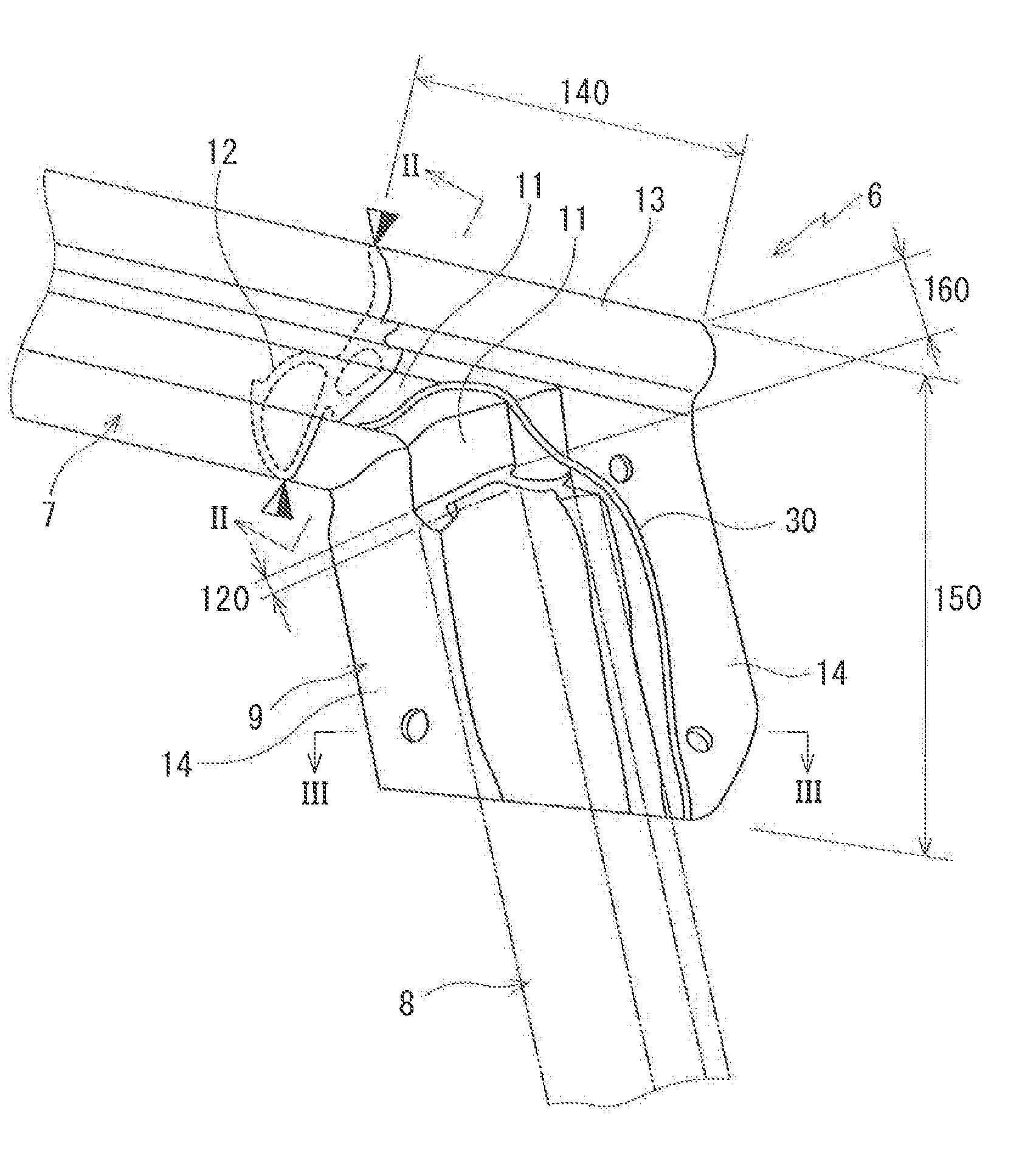
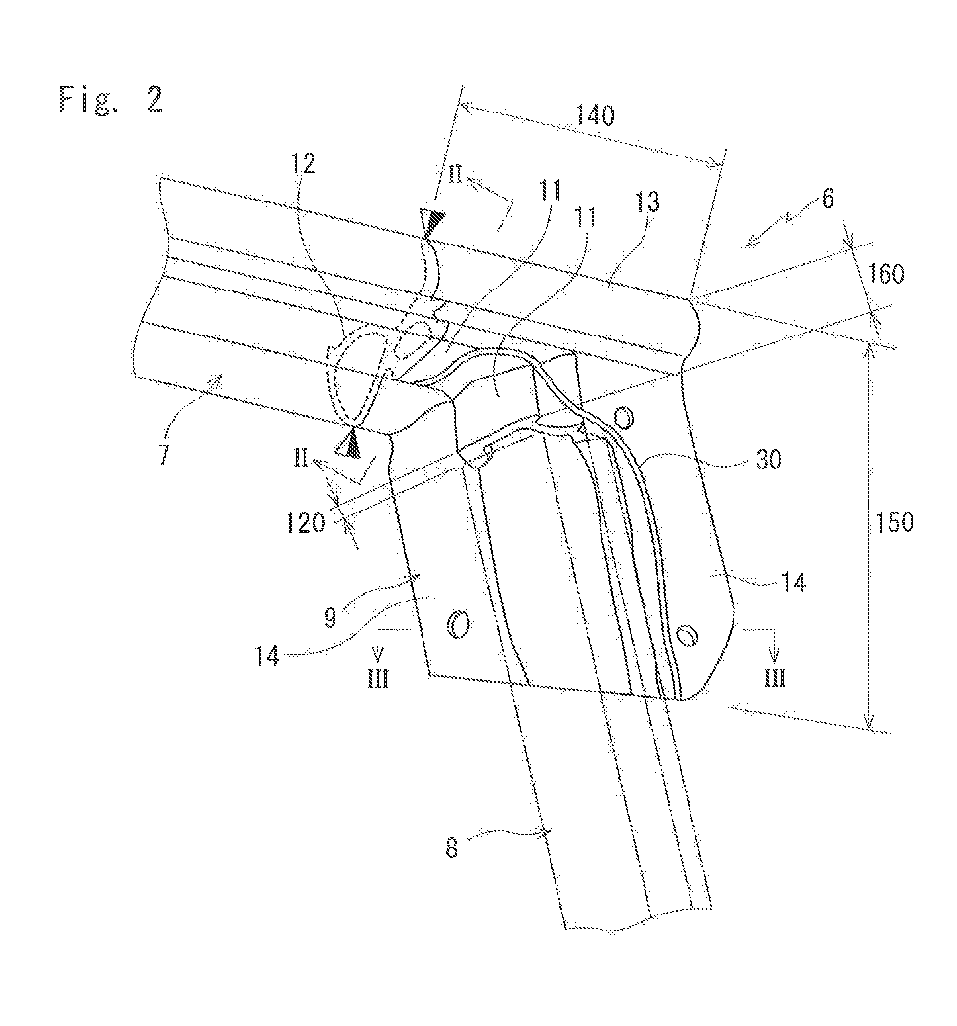
[0044]Referring to FIG. 1 to FIG. 5, FIG. 7 and FIG. 8, a door weather strip according to an embodiment of the present invention will be described. When constituents or items correspond to those in prior arts, the same symbols are used.

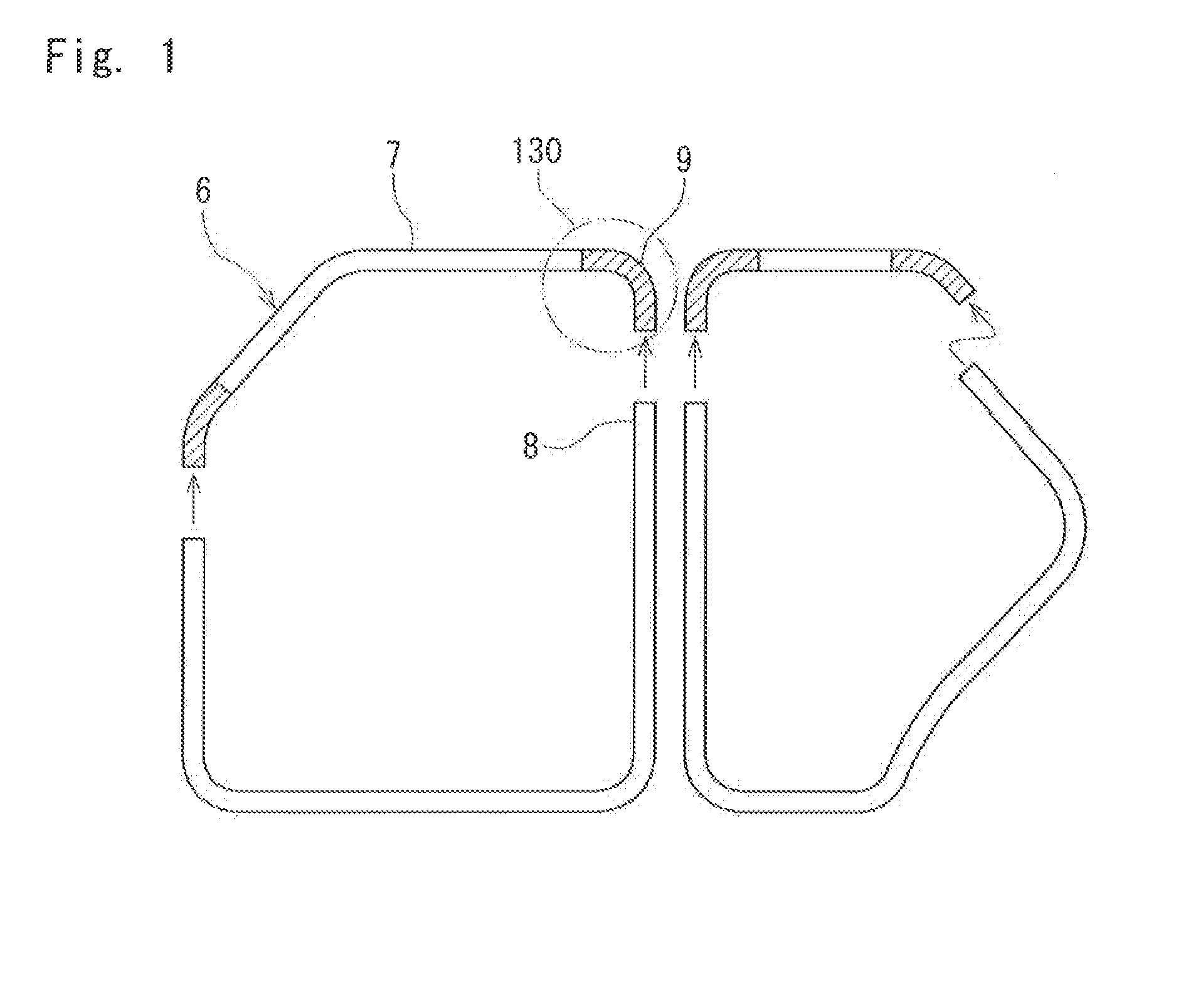
[0045]As shown in FIG. 1, a door weather strip 6 according to the embodiment of the present invention is a divisible door weather strip. According to the door weather strip 6, an upper end of a molded part 9 is connected to an end of an upper extrusion molded part 7 on a door corner part 130 and an upper end of a lower extrusion molded part 8 is detachably inserted into the molded part 9. FIG. 1 shows a state before the lower extrusion molded part 8 is inserted. As the upper end of the lower extrusion molded part 8 is inserted into the molded part 9, an annular door weather strip shown in FIG. 8 is formed.

[0046]The upper extrusion molded part 7 is installed along an upper part of a door sash 3 (may be called a part of a door panel) on a roof side (rel...


PUM


Abstract

A door weather strip includes an upper extrusion molded part installed on a door sash on a roof side; a molded part without a slit thereon, connected to the upper extrusion molded part on a door corner part; and a lower extrusion molded part installed on a vertical part of the door sash and detachably inserted into the molded part; the upper and lower extrusion molded parts and the molded part having a base bottom part and a hollow seal member formed thereon, in which: a seal bead is formed on the molded part, the seal bead extending from an inner-cabin side toward an outer-cabin side relative to the base bottom part of the molded part on the roof side and descending along an outer-cabin side of a part of the molded part on the vertical part side of the door sash.

Description

[0001]This application claims the benefit under 35 USC 119 of JP Patent Applications JP 2012-189096 filed Aug. 29, 2012 and JP 2013-155179 filed Jul. 26, 2013, the entire disclosure of which is incorporated herein by reference.BACKGROUND OF THE INVENTION[0002]The present invention relates to door weather strips installed on door sashes or door panels of automobile doors for sealing outside and inside of the automobiles by making elastic contact with door opening circumferential edges on body sides when the doors are closed.[0003]As shown in FIG. 7, a door weather strip 6 has been installed on an outer circumferential side of door sashes 3, 4 for sealing spaces between the door sashes 3, 4 and a body (body panel 100) when the doors 1,2 are closed.[0004]As shown in FIG. 8 and FIG. 9, the door weather strip 6 on a front door 1 side, for example, is formed by connecting an upper extrusion molded part 7 installed along an upper part of a door sash 3 (may be a part of a door panel) on a r...

Claims


Application Information

Patent Timeline
IPC IPC(8): B60J10/00B60J10/08
CPCB60J10/0017B60J10/086B60J10/083B60J10/233B60J10/21B60J10/86B60J10/22B60J10/248B60J10/25B60J10/27
Inventor EGUCHI, TOMOFUMI
Owner NISHIKAWA RUBBER
Why Eureka
Try Eureka