

Plasma processing apparatus and cleaning method for removing metal oxide film
Inactive Publication Date: 2014-03-06
TOKYO ELECTRON LTD
View PDF7 Cites 201 Cited by
- Summary
- Abstract
- Description
- Claims
- Application Information
AI Technical Summary
Benefits of technology
[0013]The ion filter may be a metallic plate having one or more slits. Further, each of the slits may have a width greater than or equal to a debye length. When the width of the slits is smaller than the debye length, the slits can be filled with a sheath. As a result, it is difficult for the hydrogen radicals to pass through the slits. In this case, the width of the slits is greater than the debye length, so that the hydrogen radicals easily pass through the slits. As a result, the removal efficiency of the metal oxide film can be improved.
[0014]In accordance with another aspect of the present invention, there is provided a cleaning method for removing a metal oxide film surrounded by a dielectric film, including: mounting a substrate having the dielectric film and the metal oxide film on a mounting table provided in a processing chamber; generating an excited
Problems solved by technology
However, the oxide film cannot be sufficiently reduced by the annealing process using H2 gas, and the removal of the oxide film may be insufficient.
Further, the Ar sputter
Method used
View moreImage
Smart ImageViewing Examples

Examples
 PUM
| Property | Measurement | Unit |
|---|---|---|
| Fraction | aaaaa | aaaaa |
| Length | aaaaa | aaaaa |
| Diameter | aaaaa | aaaaa |
Abstract
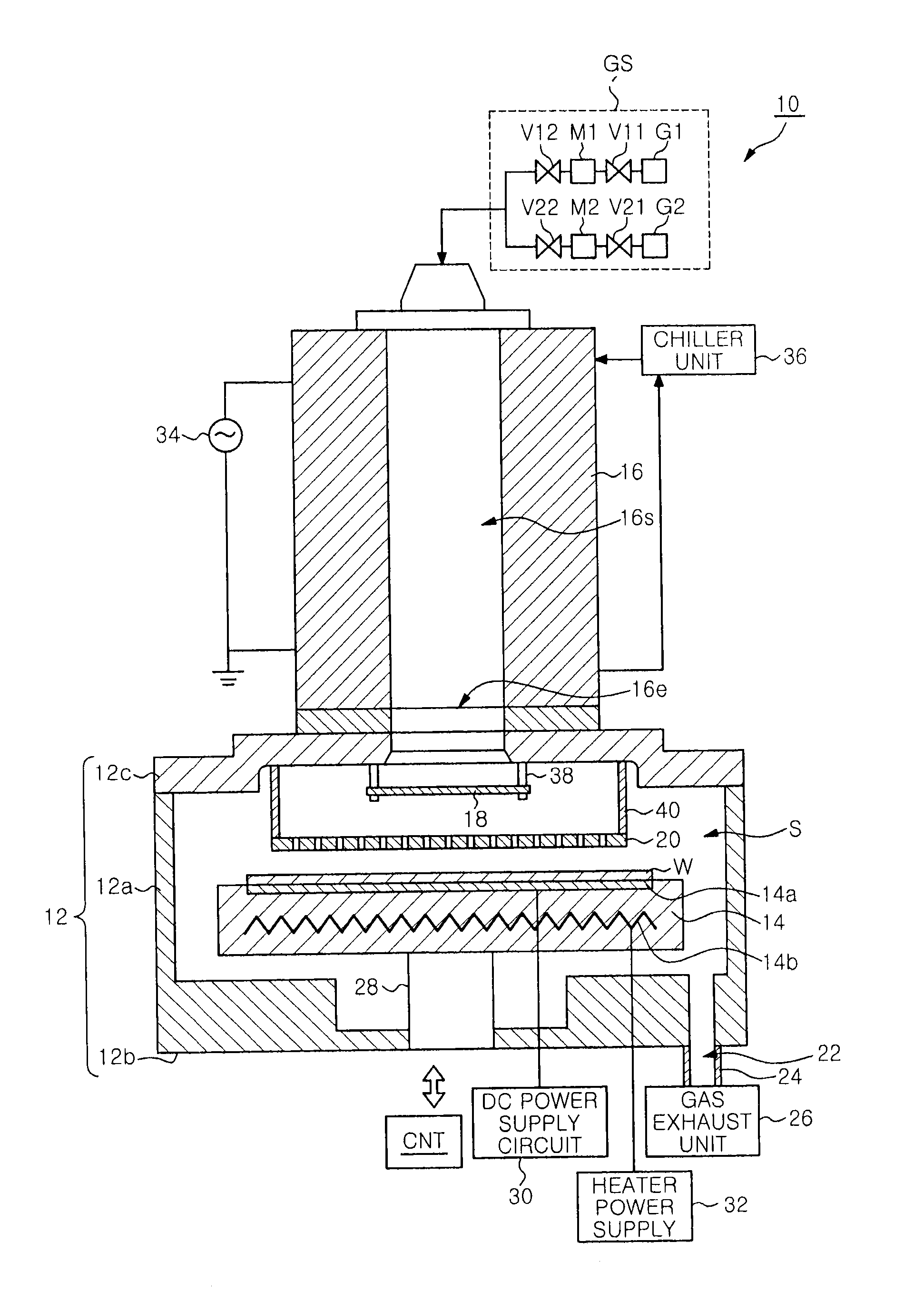
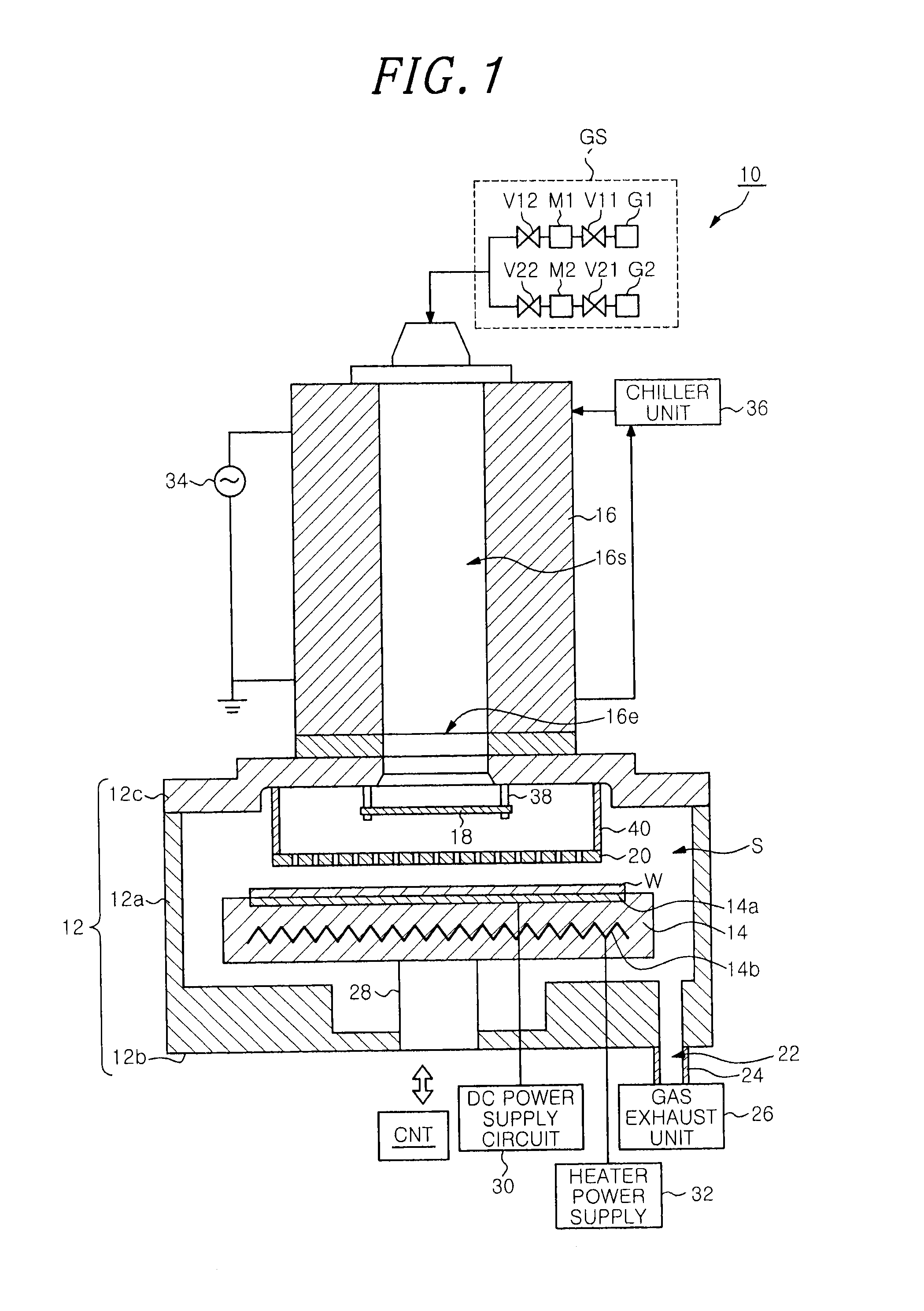
In a plasma processing apparatus, a mounting table is provided in a processing chamber, and a remote plasma generating unit is configured to generate an excited gas by exiting a hydrogen-containing gas. The remote plasma generating unit has an outlet for discharging the excited gas. A diffusion unit is provided to correspond to the outlet of the remote plasma generating unit and serves to receive the excited gas flowing from the outlet and diffuse the hydrogen active species having a reduced amount of hydrogen ions. An ion filter is disposed between the diffusion unit and the mounting table while being separated from the diffusion unit. The ion filter serves to capture the hydrogen ions contained in the hydrogen active species diffused by the diffusion unit and allow the hydrogen active species having a further reduced amount of hydrogen ions to pass therethrough the mounting table.
Description
CROSS-REFERENCE TO RELATED APPLICATIONS[0001]This application claims priority to Japanese Patent Application No. 2012-189656 filed on Aug. 30, 2012, the entire contents of which are incorporated herein by reference.FIELD OF THE INVENTION[0002]The present invention relates to a plasma processing apparatus and a cleaning method for removing a metal oxide film.BACKGROUND OF THE INVENTION[0003]A semiconductor device generally has a semiconductor element and a wiring to the semiconductor element. As for the wiring of the semiconductor apparatus, a multilayer wiring structure formed by filling a metallic material such as copper in a trench or a via hole formed in an interlayer dielectric, a so-called damascene structure, is used, for example. The damascene structure is formed by repeating a process of forming a trench and a via hole in an interlayer dielectric by etching, and a process of filling a metallic material in the trench and the via hole.[0004]A surface of the wiring manufactured...
Claims
Login to View More Application Information
Patent Timeline
 IPC IPC(8): H01L21/02
CPCH01L21/02041H01L21/02065H01J37/32357H01J37/32422H01J37/32449H01J37/32862
InventorYASUMURO, CHIAKISAKUMA, TAKASHIYOKOYAMA, OSAMUTOSHIMA, HIROYUKIHARA, MASAMICHIHAN, CHEONSOOTAKANASHI, MORIHIROFUJISATO, TOSHIAKI
OwnerTOKYO ELECTRON LTD