Systems and methods for shim current calculation

a shim current and calculation method technology, applied in the field of magnetic resonance imaging, can solve the problems of affecting the uniformity of the magnetic field, the inhomogeneity of the imager, and the field produced by the primary magnet within

Active Publication Date: 2014-03-06
GENERAL ELECTRIC CO
View PDF2 Cites 21 Cited by
  • Summary
  • Abstract
  • Description
  • Claims
  • Application Information

AI Technical Summary

Benefits of technology

[0011]FIG. 3 is a process flow diagram illustrating an embodiment of a method for producing a magnetic fie...

Problems solved by technology

However, the magnetic field produced by the primary magnet within an MRI imager is typically inhomogeneous, for example, due to factors such as the presence of materials (e.g., iron) in the environment that are susceptible to magnetization in the presence of the primary magnet.
Further, when the subject of interest is placed within the MRI imager for examination, additional inhomogeneities may be int...

Method used


Image

  • Systems and methods for shim current calculation
  • Systems and methods for shim current calculation
  • Systems and methods for shim current calculation

Examples


Embodiment Construction

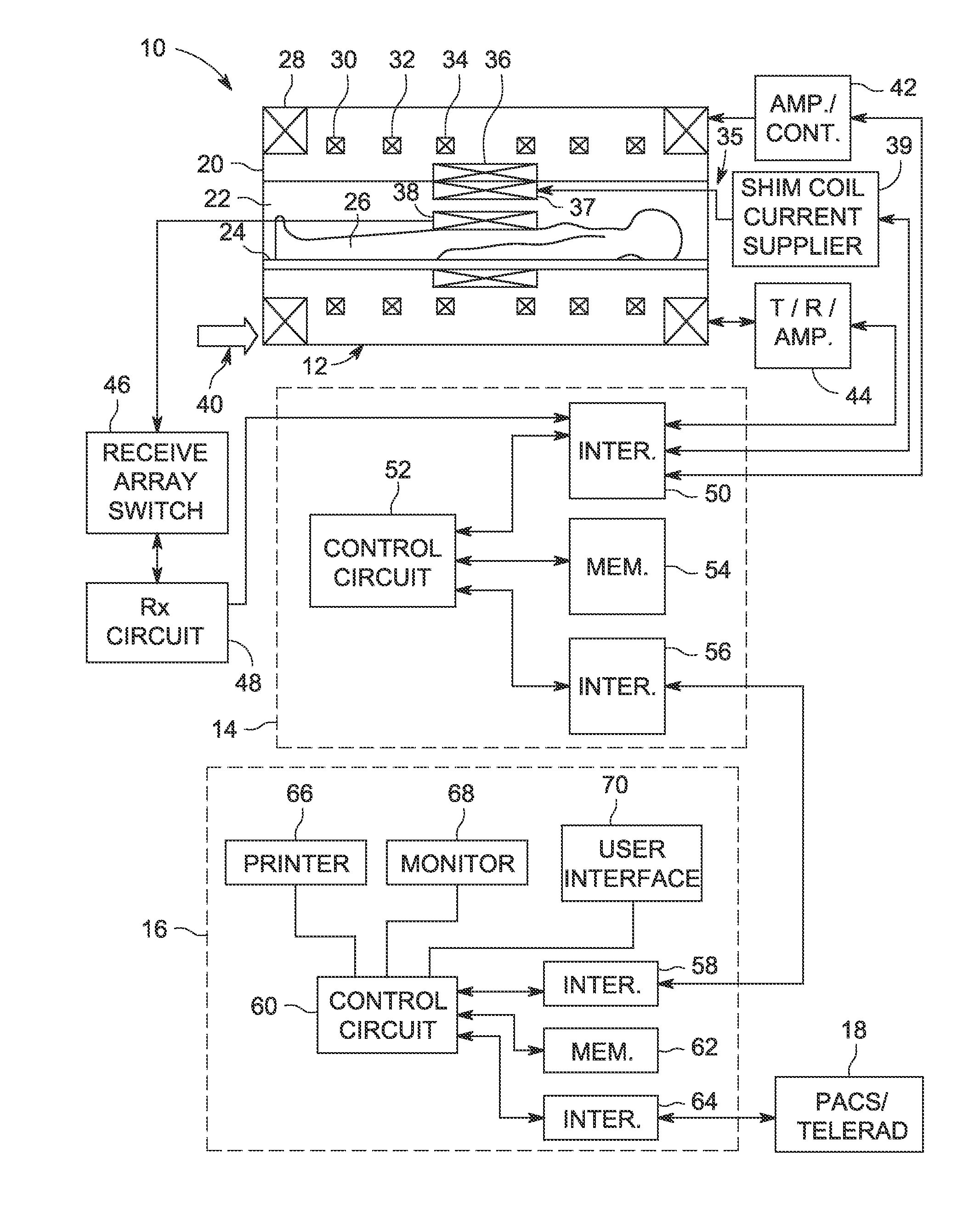
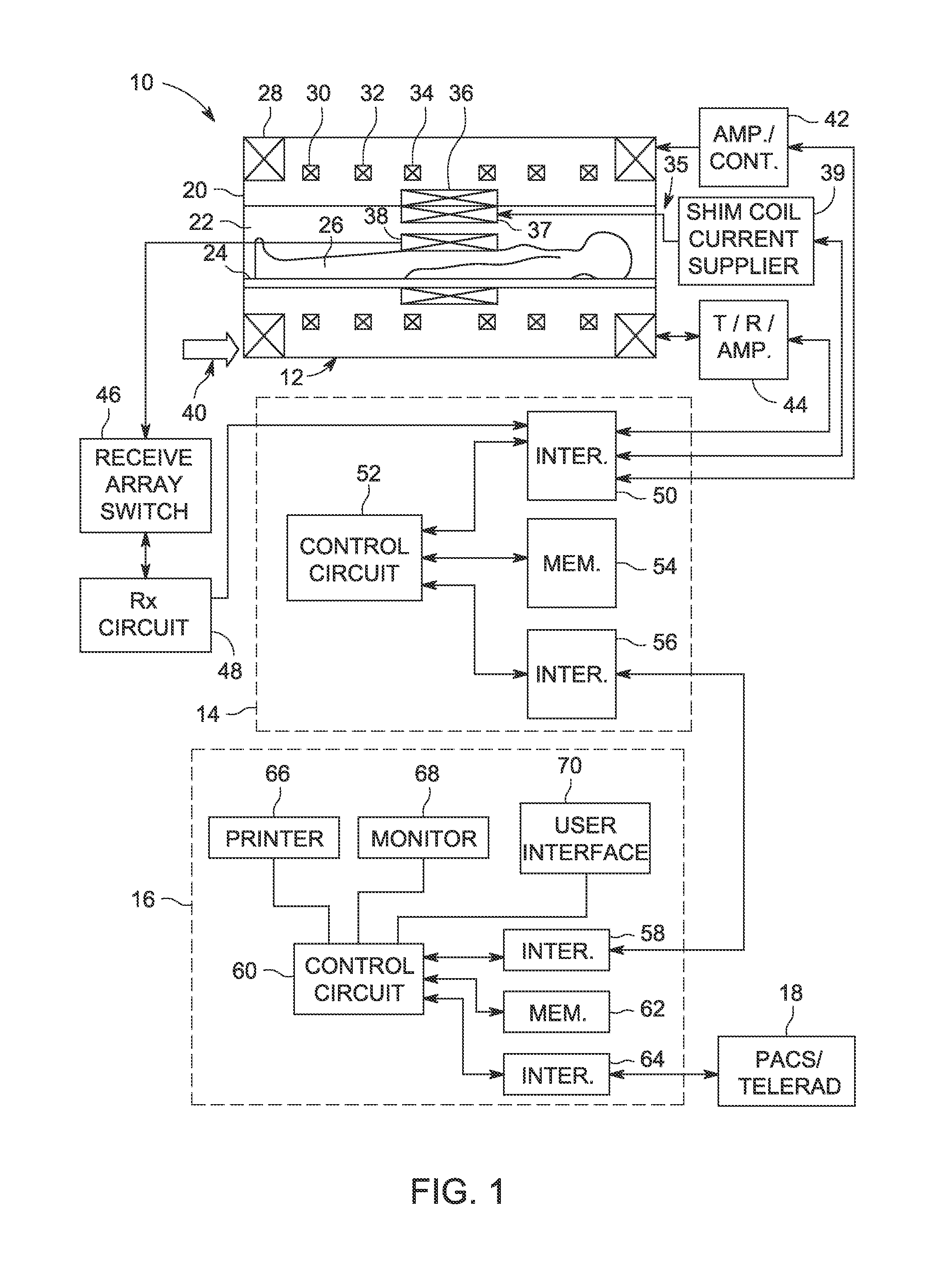
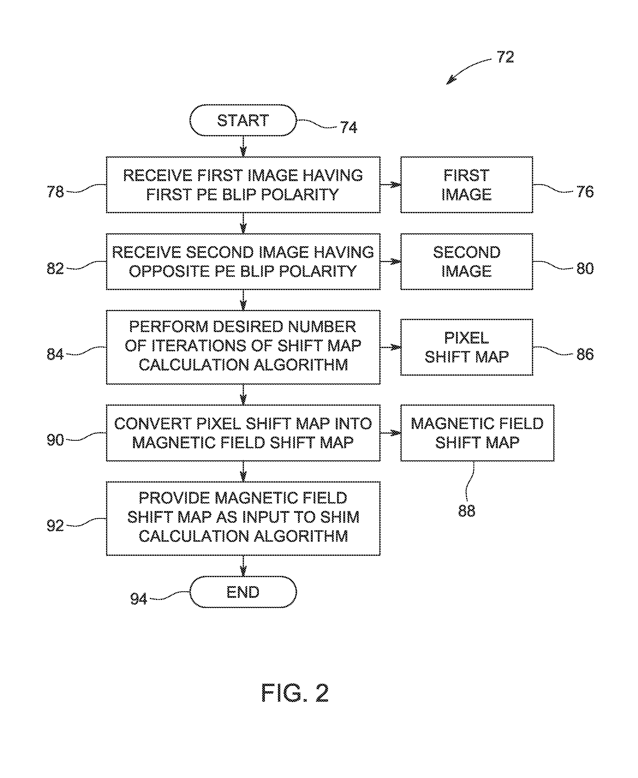
[0015]As described in more detail below, provided herein are systems and methods for shimming a magnetic resonance (MR) magnet. In certain embodiments, a pixel shift map corresponding to a pixel difference between a forward spatial encoding polarity MR coil image and a reverse spatial encoding polarity MR coil image may be converted into a magnetic field shift map that may be utilized in a shim calculation process. For example, in some embodiments, the magnetic field shift map may be provided as an input to a linear or high order shim calculation algorithm that may be implemented to determine an appropriate shim current to pass through a shim coil. Further, in some embodiments, the pixel shift map may be determined by iteratively minimizing the distance between the forward and reverse spatial encoding polarity MR images until only the low order features (e.g., the first and second order features) stabilize, since the high order features may not be capable of being shimmed. In this m...


PUM


Abstract

A method includes receiving a forward spatial encoding polarity magnetic resonance (MR) coil image and a reverse spatial encoding polarity MR coil image generated from data obtained with a magnetic field gradient that is reversed with respect to the magnetic field gradient with which the forward spatial encoding polarity MR coil image is acquired. The method also includes performing an iterative shift map calculation algorithm to determine a pixel shift map corresponding to a minimized difference between the forward and reverse spatial encoding polarity MR coil images, converting the pixel shift map into a magnetic field shift map by determining a magnetic field value corresponding to each pixel in the pixel shift map, and providing the magnetic field shift map as an input to a shim calculation process that includes determining a level of at least one shim current.

Description

BACKGROUND[0001]The subject matter disclosed herein relates to magnetic resonance imaging (MRI), and, more particularly, to systems and methods for shim current calculation for shimming a magnet.[0002]In general, magnetic resonance imaging (MRI) examinations are based on the interactions among a primary magnetic field, a radiofrequency (RF) magnetic field and time varying magnetic gradient fields with gyromagnetic material having nuclear spins within a subject of interest, such as a patient. Certain gyromagnetic materials, such as hydrogen nuclei in water molecules, have characteristic behaviors in response to external magnetic fields. The precession of spins of these nuclei can be influenced by manipulation of the fields to produce RF signals that can be detected, processed, and used to reconstruct a useful image.[0003]The magnetic fields used to generate images in MRI systems include a magnetic field that is produced by a primary magnet. A series of gradient fields are produced by...

Claims


Application Information

Patent Timeline
IPC IPC(8): G01R33/56G01R33/341
CPCG01R33/56563G01R33/243
Inventor KOCH, KEVIN MATTHEWPRINTZ, ERIC M.
Owner GENERAL ELECTRIC CO
Why Eureka
Try Eureka