Magnetic core for magnetic component with winding, containing improved means of cooling

Inactive Publication Date: 2014-03-06
GE ENERGY POWER CONVERSION TECH
View PDF2 Cites 12 Cited by
  • Summary
  • Abstract
  • Description
  • Claims
  • Application Information

AI Technical Summary

Problems solved by technology

In particular, a magnetic component with optimised efficiency is generally of larger size and more costly than a mag

Method used


Image

  • Magnetic core for magnetic component with winding, containing improved means of cooling
  • Magnetic core for magnetic component with winding, containing improved means of cooling
  • Magnetic core for magnetic component with winding, containing improved means of cooling

Examples


Embodiment Construction

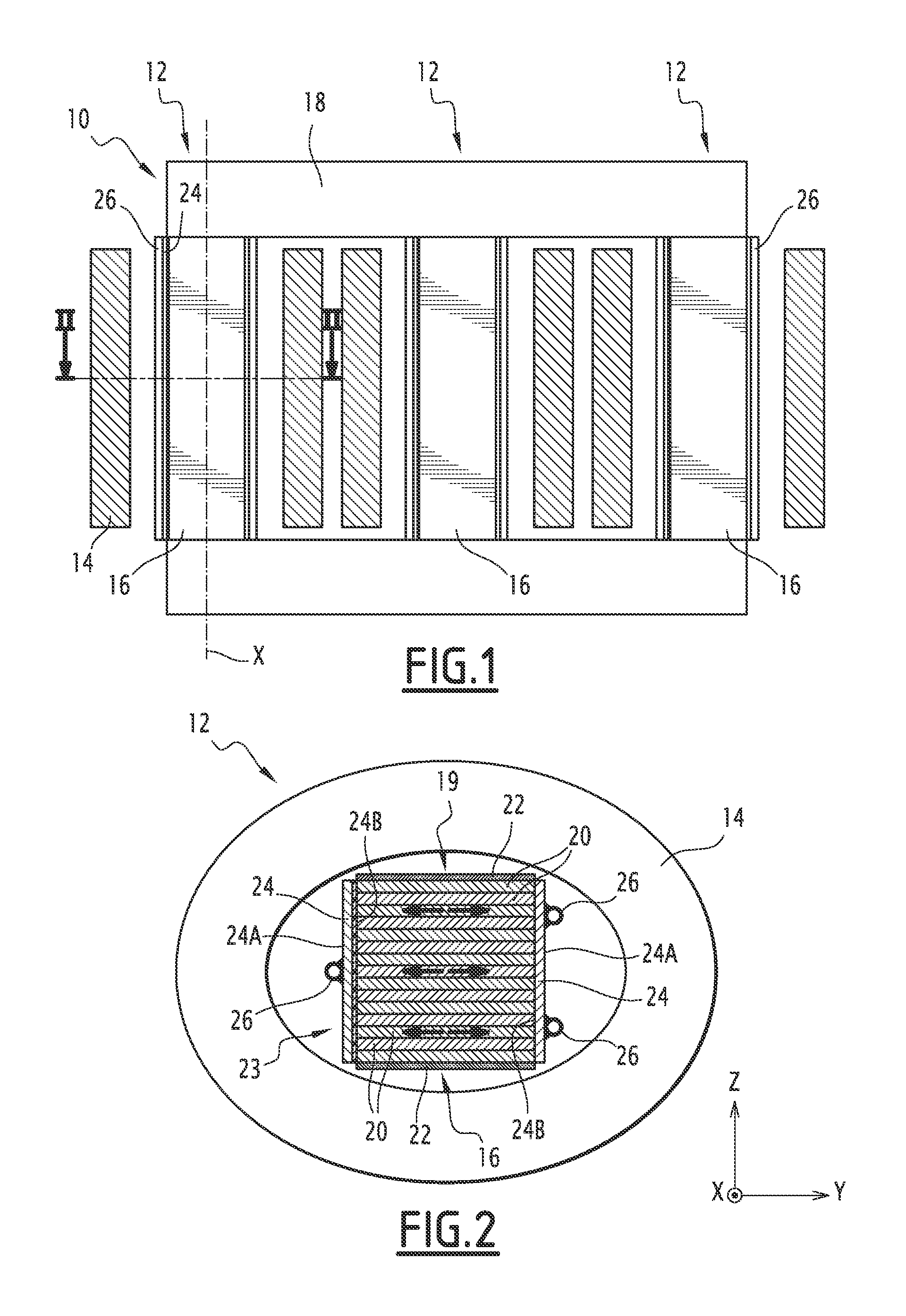
[0017]FIG. 1 is a representation of a three-phase set 10 containing three induction coils 12. The whole of the electrical circuit, including the connections, is of classic design and will not therefore be described in any more detail.

[0018]The three coils 12 are identical, and therefore only one of them will be described below.

[0019]Each induction coil 12 comprises a winding 14, consisting of a conductive element wound for example in a spiral shape around a longitudinal axis X. The conductive element is for example a wire, or produced using a hollow rolling or sheet.

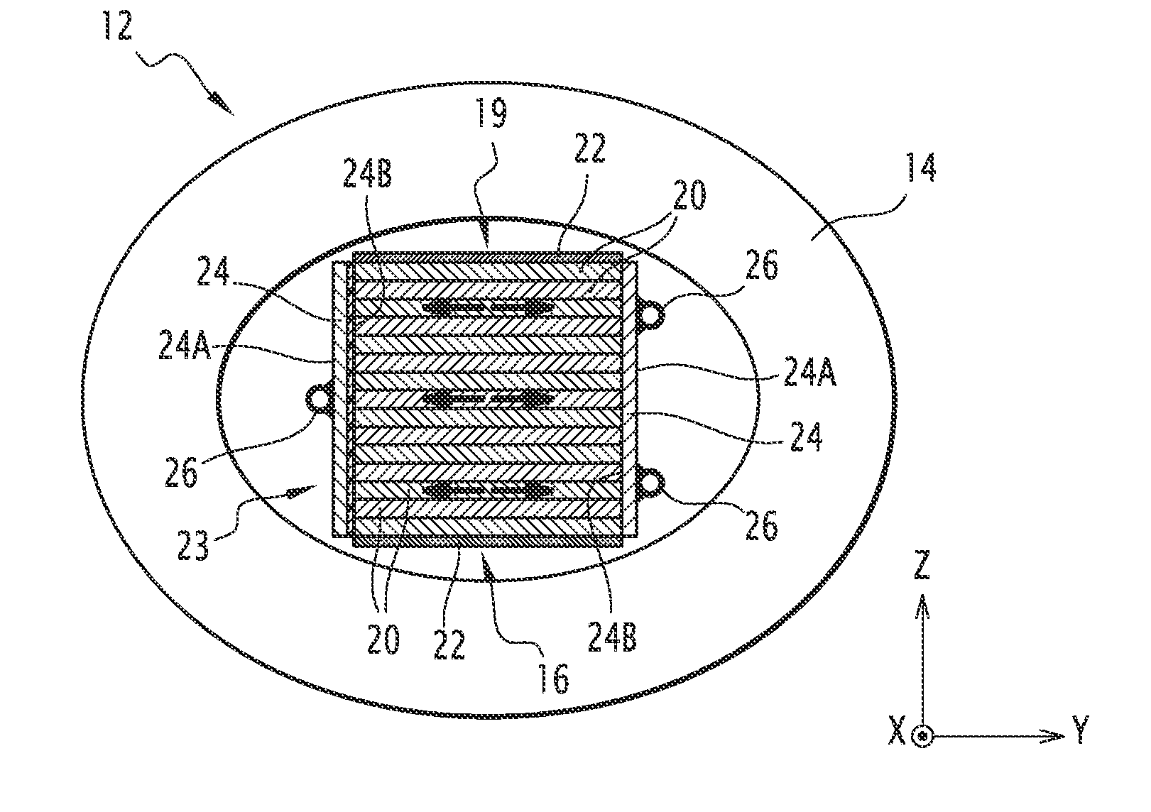
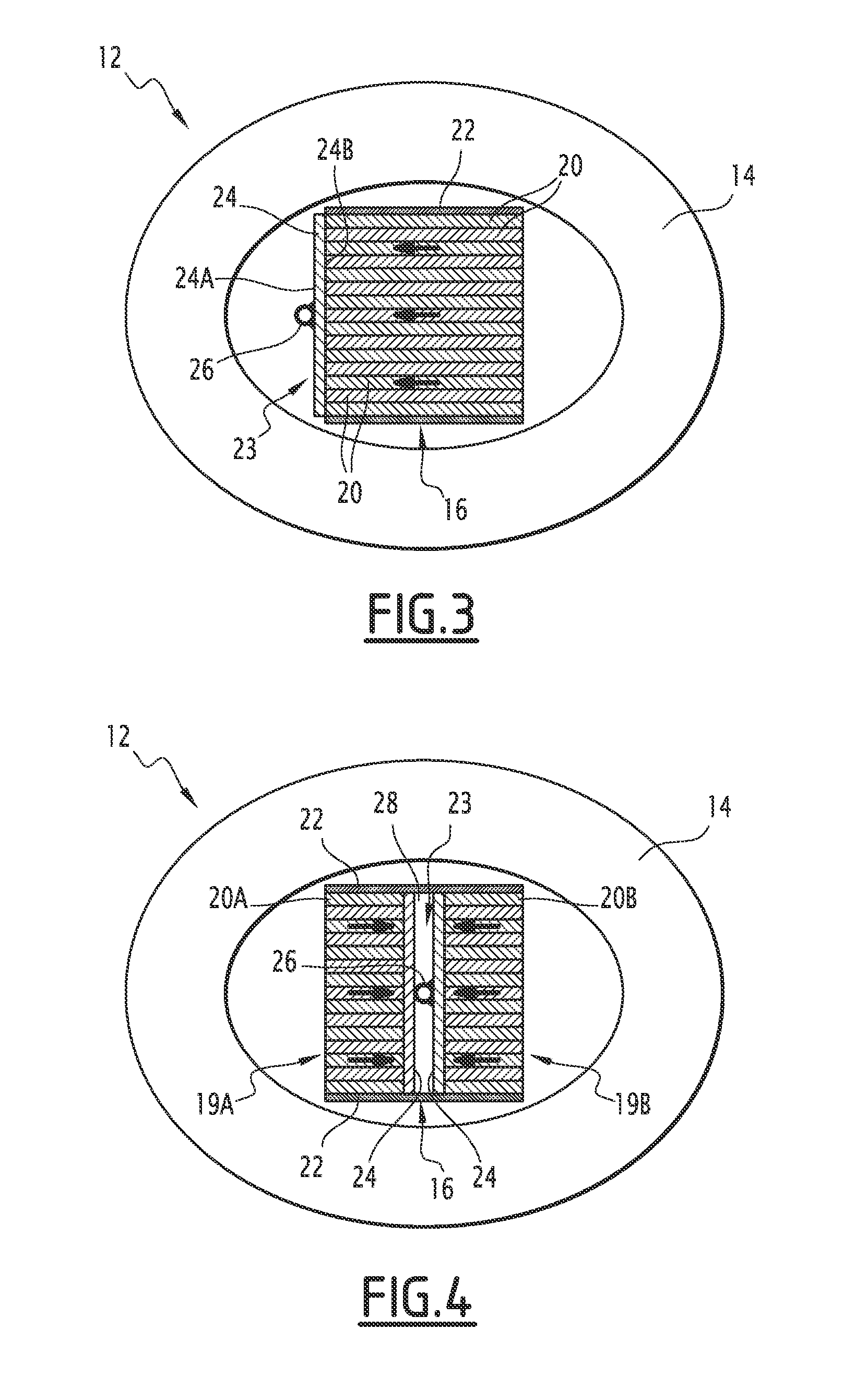
[0020]Each coil 12 also comprises a magnetic core 16, extending in the direction of the longitudinal axis X, and as a result the winding 14 coaxially surrounds the magnetic core 16.

[0021]In standard formation, the three magnetic cores 16 are arranged in parallel and connected to a cylinder consisting of elements 18 for backflow from the magnetic core.

[0022]Each magnetic core 16 consists, in a known fashion, of a pluralit...


PUM


Abstract

A magnetic core extends in a longitudinal direction and contains at least one stacking of sheets consisting of magnetic material and stacked in a direction of stacking perpendicular to the longitudinal direction, at least one plate of heat-conducting material, presenting first and second opposing faces, and at least one cooling tube positioned in contact with the said first face of the plate in which a heat-bearing fluid is designed to circulate. The plate extends in a plane parallel to the longitudinal direction and to the direction of stacking, its second face being positioned in thermal contact with the sheets in the stacking.

Description

BACKGROUND OF THE INVENTION[0001]Embodiments of the present invention relate to a magnetic core for a magnetic component with winding, such as an induction coil or transformer, containing improved means of cooling.[0002]There thus exist magnetic components, especially induction coils, which contain a winding that surrounds such a magnetic core.[0003]Usually, a magnetic component with winding is assessed according to three criteria, namely: good efficiency (limited losses), reduced size and reduced cost.[0004]These three criteria are not, generally speaking, compatible. In particular, a magnetic component with optimised efficiency is generally of larger size and more costly than a magnetic component sized to offer reduced cost. This means that one of the three above-mentioned criteria is usually optimized to the detriment of at least one of the two others. It is observed that the current trend in the state of the art involves giving priority to cost and size criteria to the detriment...

Claims


Application Information

Patent Timeline
IPC IPC(8): H01F27/10
CPCH01F27/10H01F27/08H01F27/22H01F27/245
Inventor DELANOE, JEROMEGUETTE, ERIC
Owner GE ENERGY POWER CONVERSION TECH
Why Eureka
Try Eureka