

In-Water Voltage Gradient Detector
a voltage gradient and detector technology, applied in the field of voltage gradient detectors, can solve the problems of dangerous underwater lighting conditions, inability to accurately detect voltage gradients, etc., to achieve convenient location of gradient sources, increase voltage, and facilitate electrode pairing
- Summary
- Abstract
- Description
- Claims
- Application Information
AI Technical Summary
Benefits of technology
Problems solved by technology
Method used
Image

Examples
Embodiment Construction
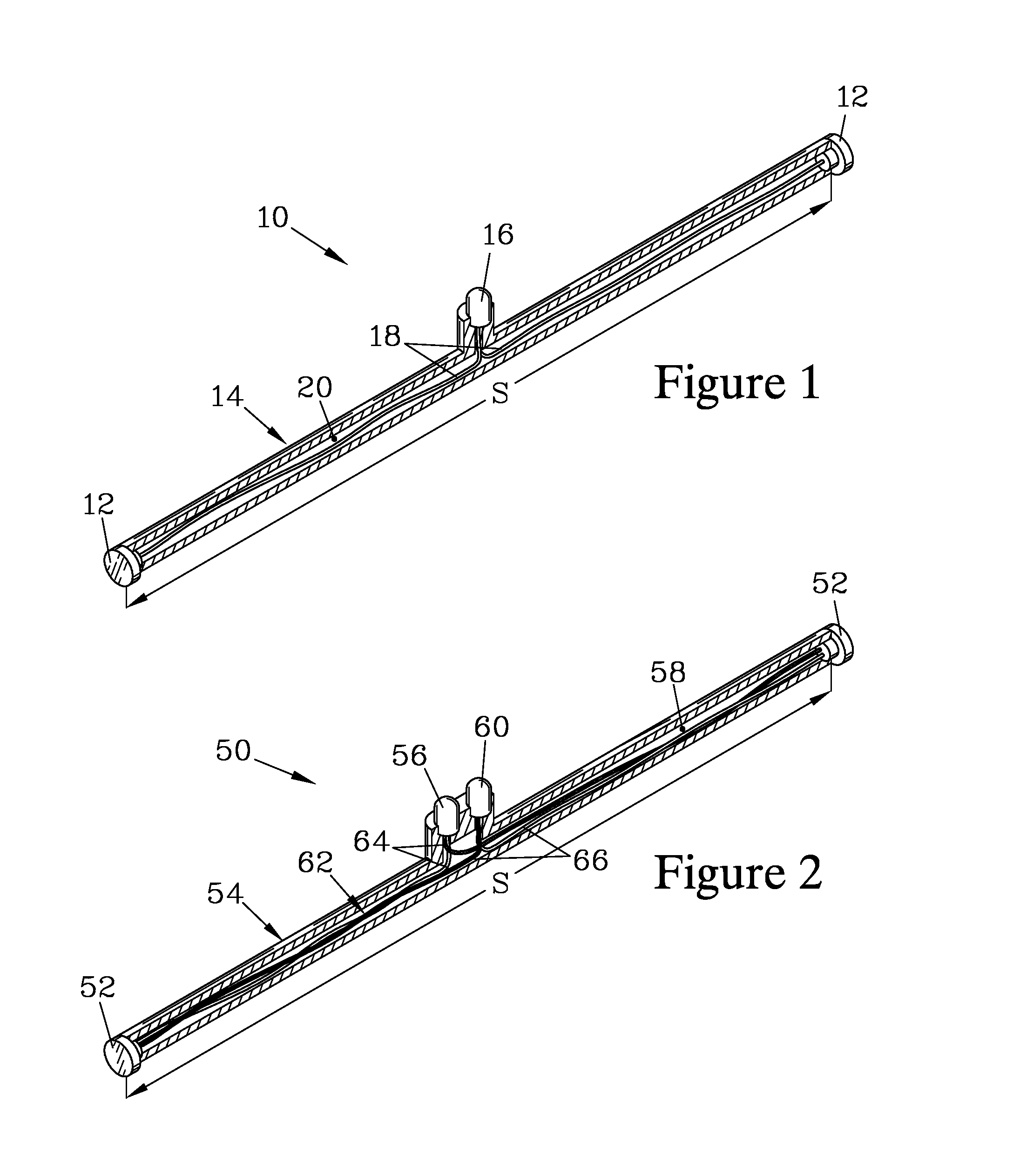
[0039]FIG. 1 is an isometric view of one embodiment of an in-water voltage gradient detector 10 of the present invention. For reasons discussed below, the gradient detector 10 has characteristics that make it suitable for providing notice to an individual when the voltage gradient in the direction measured is above a threshold level where an individual entering the water would be likely to be harmed by the voltage gradient. The device 10 has a pair of spaced apart electrodes 12 that are maintained at a separation S by a hollow spacer 14, to which the electrodes 12 are sealably attached.
[0040]An LED 16 resides between the electrodes 12, and is sealably attached to the spacer 14 such that its electrical contacts can be connected to the first pair of electrodes 12 by a pair of conductors 18. The sealable attachment of the electrodes 12 and the LED 16 to the spacer 14 serves to electrically isolate the electrodes 12 from each other, except for their connection through the LED 16 via the...
PUM
 Abstract
Description
Claims
Application Information