Unified rasterization and ray tracing rendering environments

a ray tracing and rasterization technology, applied in the field of 3d rendering, can solve the problems of ray tracing not being pipelined in the same way as rasterization, and it is difficult and time-consuming to produce sophisticated rendering outputs using rasterization

Active Publication Date: 2014-03-06
IMAGINATION TECH LTD
View PDF2 Cites 88 Cited by
  • Summary
  • Abstract
  • Description
  • Claims
  • Application Information

AI Technical Summary

Benefits of technology

[0012]Other constituent elements of architectures and processes implemented on such architectures can include ray population control features, w

Problems solved by technology

However, it is difficult and time consuming to produce sophisticated rendering outputs using rasterization
However, ray tracing cannot be pipelined in the same way as rasterization,

Method used


Image

  • Unified rasterization and ray tracing rendering environments
  • Unified rasterization and ray tracing rendering environments
  • Unified rasterization and ray tracing rendering environments

Examples


Embodiment Construction

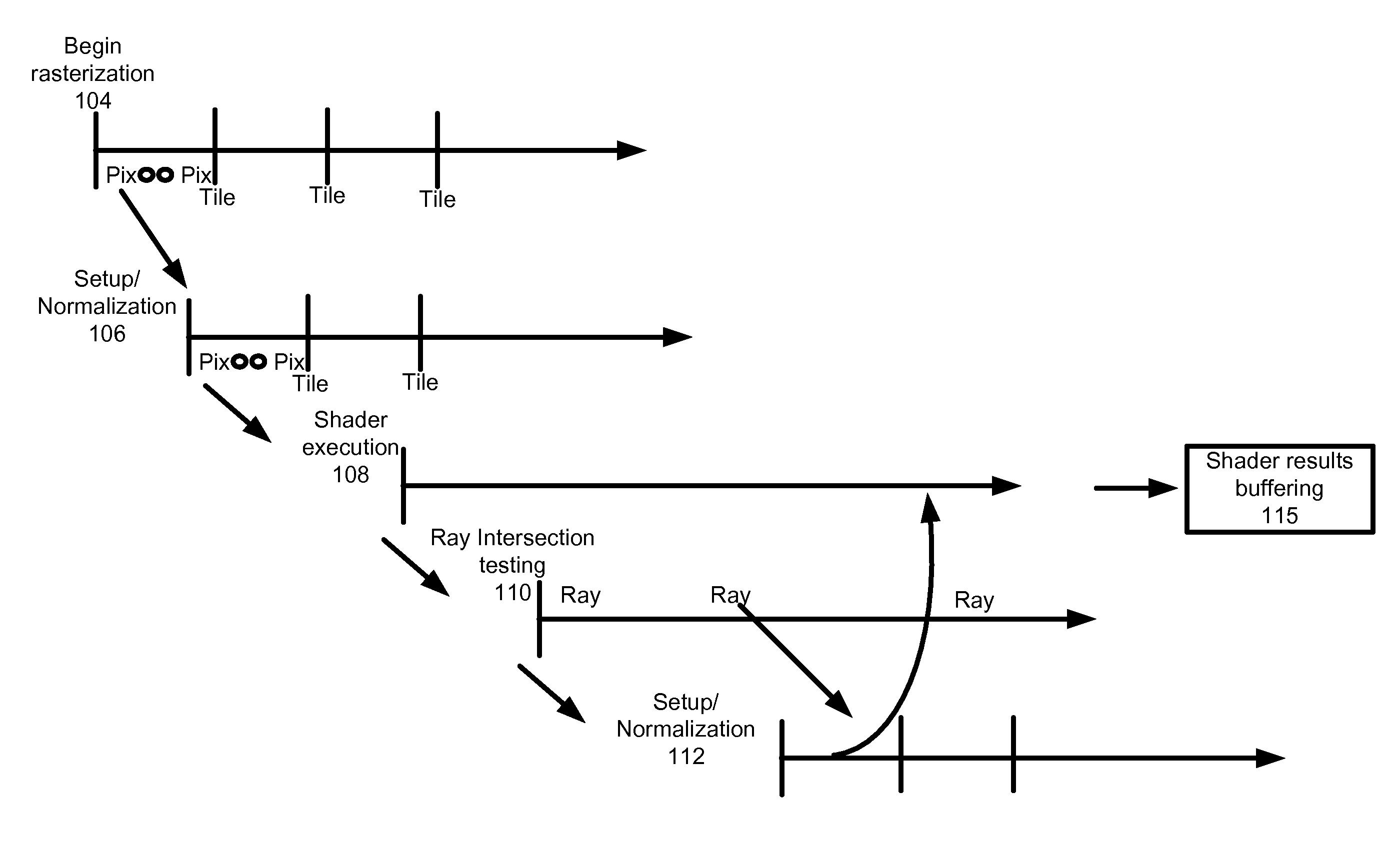
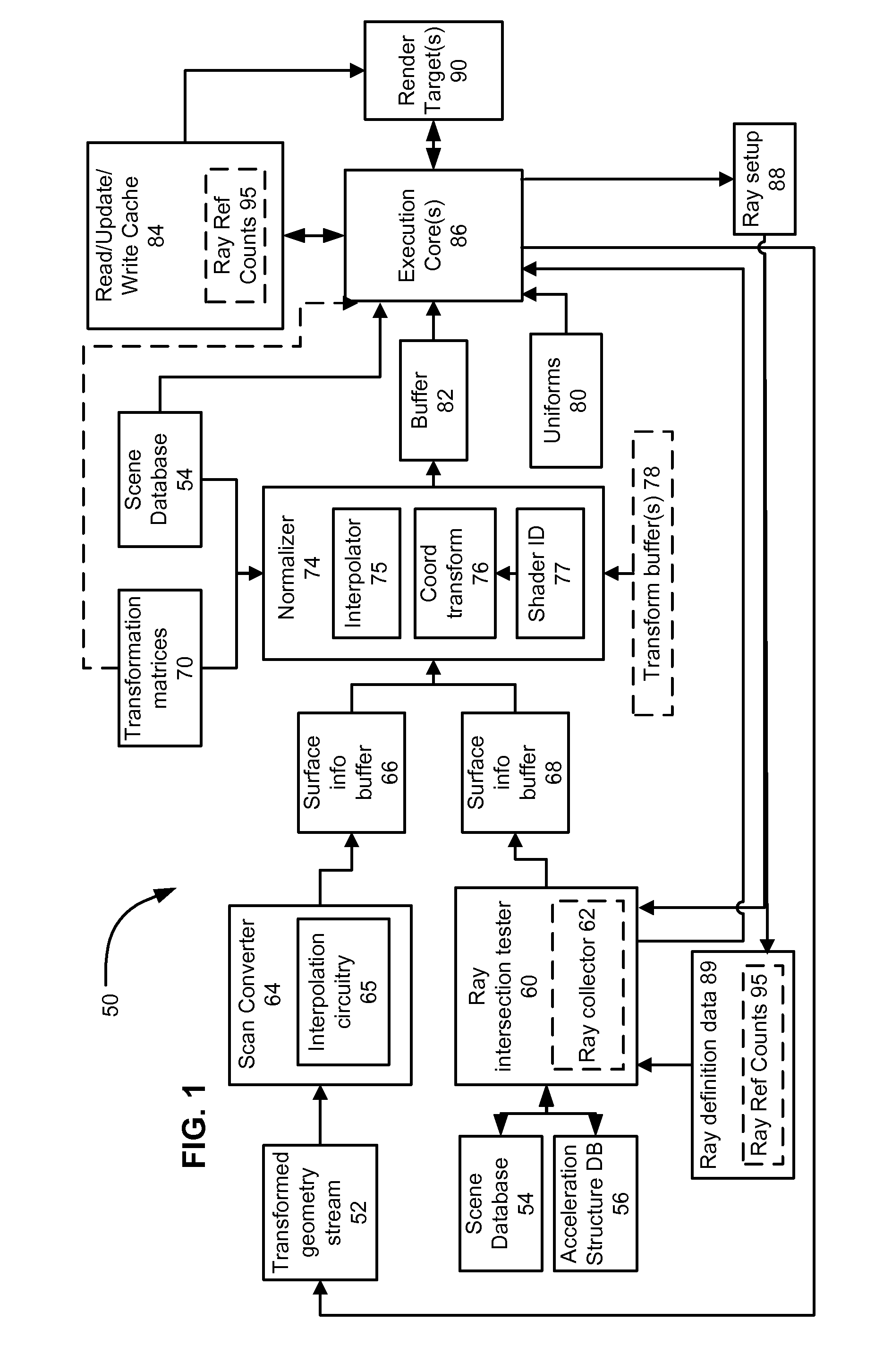
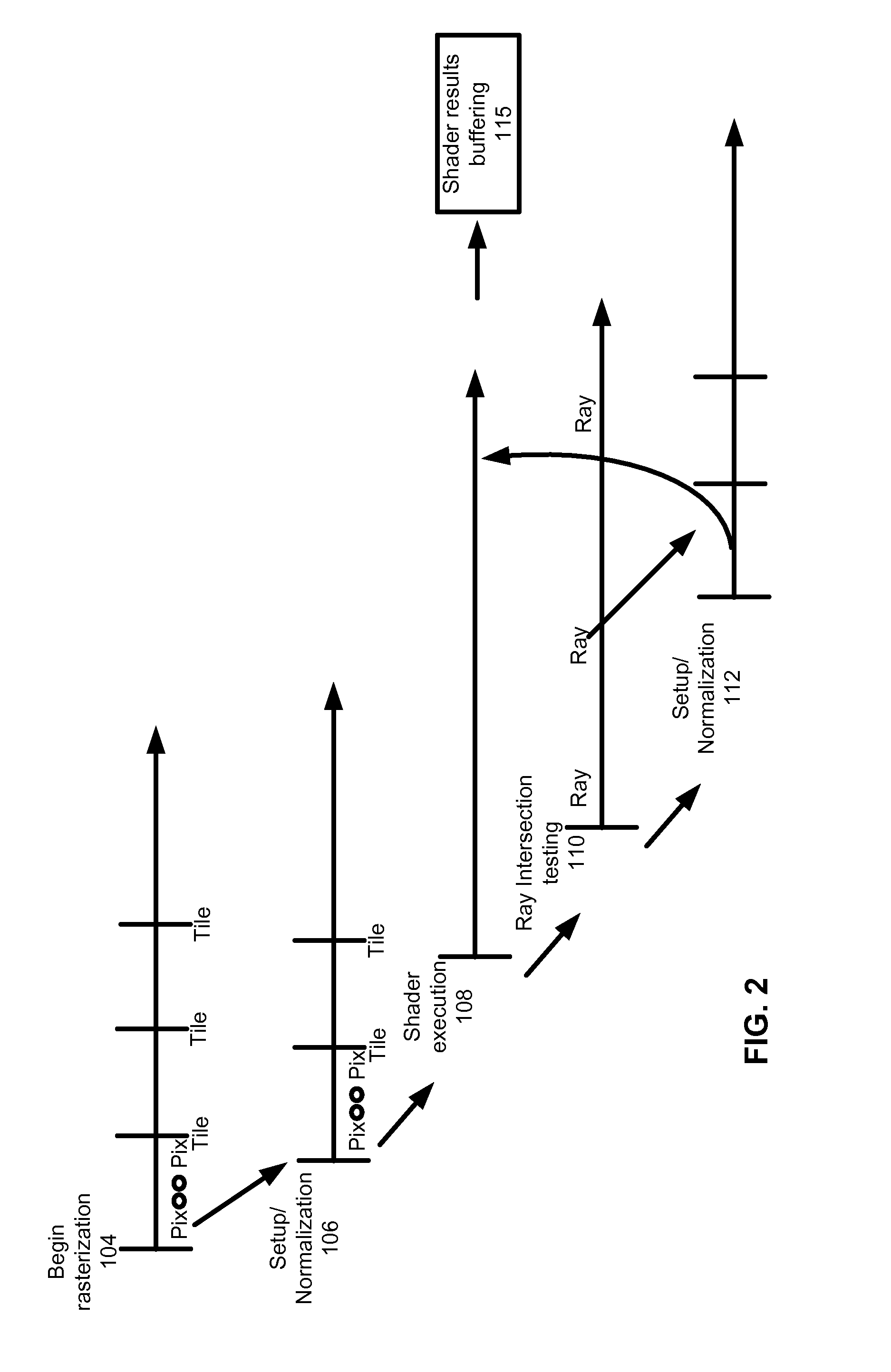
[0027]The following disclosure includes multiple examples of graphics processing architectures, in which a unified computation resource performs shading work concurrently for surfaces identified by both ray tracing and by rasterization techniques. In one aspect, a unified computation resource executes shaders based on a normalized set of inputs, and a given surface is shaded by an associated shader module, regardless whether that surface is to be shaded responsive to a ray intersection or during rasterization. In another aspect, different shader code modules may exist for shading ray tracing intersections and for rasterization. In implementations according to such aspects, surface shaders for rasterization offer a capability to emit rays to be intersection tested, and to perform shading, in dependence on the results of intersection testing that ray.

[0028]In some implementations of the disclosure, there are multiple concurrently executing processes that either have dedicated hardware...


PUM


Abstract

A graphics processor architecture provides for scan conversion and ray tracing approaches to visible surface determination as concurrent and separate processes. Surfaces can be identified for shading by scan conversion and ray tracing. Data produced by each can be normalized, so that instances of shaders, being executed on a unified shading computation resource, can shade surfaces originating from both ray tracing and rasterization. Such resource also may execute geometry shaders. The shaders can emit rays to be tested for intersection by the ray tracing process. Such shaders can complete, without waiting for those emitted rays to complete. Where scan conversion operates on tiles of 2-D screen pixels, the ray tracing can be tile aware, and controlled to prioritize testing of rays based on scan conversion status. Ray population can be controlled by feedback to any of scan conversion, and shading.

Description

CROSS REFERENCE TO RELATED APPLICATIONS[0001]This application claims priority from U.S. Provisional Patent App. No. 61 / 678,055, filed on Jul. 31, 2012, entitled “UNIFIED RASTERIZATION AND RAY TRACING RENDERING ENVIRONMENTS”, which is incorporated by reference in its entirety herein for all purposes.BACKGROUND[0002]1. Field[0003]The following relates to approaches to 3-D rendering and architectures for performing 3-D rendering.[0004]2. Related Art[0005]3-D rendering involves producing images from 3-D scene descriptions. The images can be photorealistic, or achieve other objectives. For example, animated movies can be produced using 3-D rendering techniques.[0006]A variety of techniques for performing 3-D rendering are known. Two principal categories of 3-D rendering are rasterization oriented approaches, and ray tracing oriented approaches. Rasterization involves defining a view point for a 3-D scene containing geometry and a pixel array to be rendered from the scene. In most rasteri...

Claims


Application Information

Patent Timeline
IPC IPC(8): G06T15/80G06T15/06
CPCG06T15/06G06T15/80G06T15/005G06T1/20G06T2200/04G06T2200/28G06T2207/20021
Inventor HOWSON, JOHN W.PETERSON, LUKE TILMAN
Owner IMAGINATION TECH LTD
Why Eureka
Try Eureka