Driving method of liquid crystal display device

a liquid crystal display and driving method technology, applied in the field of driving methods of liquid crystal display devices, can solve the problems of increasing reducing the power consumption of the backlight, and increasing the rate of the screen having little color information, so as to reduce power consumption, suppress the power of the backlight, and increase the luminance of the screen

Active Publication Date: 2014-03-06
JAPAN DISPLAY INC
View PDF5 Cites 3 Cited by
  • Summary
  • Abstract
  • Description
  • Claims
  • Application Information

AI Technical Summary

Benefits of technology

[0014]According to the present invention, under the high-illuminance environment, the luminance of the screen is increased by mixing other colors into a predetermined color also when a monochromatic image is to be displayed. Thus, since it is allowed to visibly confirm the screen by suppressing the power of the backlight even when the

Problems solved by technology

Therefore, when it frequently occurs that the display device is used under a high-illuminance environment, the power consumption of the backlight is increased.
However, the image signal is supplied from the outside also in this case and since it is not the system configure

Method used


Image

  • Driving method of liquid crystal display device
  • Driving method of liquid crystal display device
  • Driving method of liquid crystal display device

Examples


embodiment 1

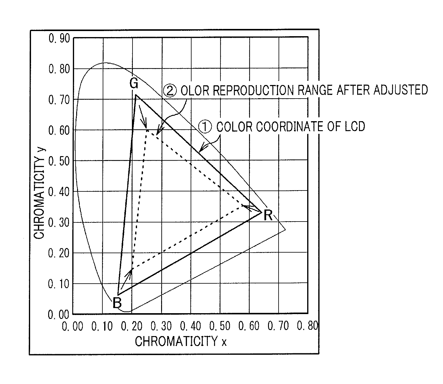
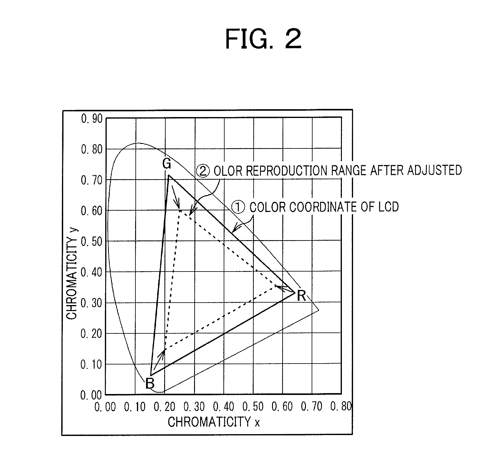
[0039]FIG. 4 is a chromaticity diagram illustrating an example that the present invention has been applied to an actual product. In FIG. 4, a solid-line triangle indicates sRGB (70% in color reproducibility) and a dotted-line triangle indicates sRGB (50% in reproducibility). That is, the range of the solid-line triangle is used under the normal environment and the range of the dotted-line triangle is used under the high-illuminance environment. Although the shape of the dotted-line triangle is slightly different from that illustrated in FIG. 2, the shape differs depending on setting of the range to be color-reproduced and the luminance. That is, the shape of the triangle is changed depending on how the range of to be color-reproduced in sRGB (50% in color reproducibility) is set.

[0040]FIG. 5 illustrates examples of values of 8-bit-based gradation with which red, green and blue are displayed under the normal environment, that is, in sRGB (70% in color reproducibility), and values of ...


PUM


Abstract

Under a normal environment, when red, green and blue displays are to be performed, the displays are performed singly by a red pixel, a green pixel and a blue pixel respectively, and under a high-illuminance environment, when the red display is to be performed, the display is performed by also shining the pixels other than the red pixel simultaneously, when the green display is to be performed, the display is performed by also shining the pixels other than the green pixel simultaneously, and when the blue display is to be performed, the display is performed by also shining the pixels other than the blue pixel simultaneously, thereby increasing the luminance of a screen. In this case, although the chromaticity of each color is lowered, since the luminance works more predominantly on the image quality under the high-illuminance environment than the chromaticity, image quality degradation does not occur.

Description

CLAIM OF PRIORITY[0001]The present application claims priority from Japanese Patent Application JP 2012-188667 filed on Aug. 29, 2012, the content of which is hereby incorporated by reference into this application.BACKGROUND OF THE INVENTION[0002]1. Field of the Invention[0003]The present invention relates to a display device and more particularly relates to a liquid crystal display device allowing to maintain a contrast without increasing power consumption even under a light environment.[0004]2. Description of the Related Art[0005]In the liquid crystal display device, a TFT substrate on which pixels having pixel electrodes and thin film transistors (TFT) are arranged in a matrix and a counter substrate on which color filters and the like are formed at places corresponding to the pixel electrodes of the TFT substrate are arranged in opposition to each other, and a liquid crystal is nipped and held between the TFT substrate and the counter substrate. Then, an image is formed by contr...

Claims


Application Information

Patent Timeline
IPC IPC(8): G09G3/18
CPCG09G3/18G09G3/2003G09G3/3648G09G2340/06G09G2360/144
Inventor OKAZAKI, KENGOARISATO, KOZONAKAMURA, TOMOKI
Owner JAPAN DISPLAY INC
Why Eureka
Try Eureka