Inverter device
a technology of inverter device and inverter, which is applied in the direction of ac-dc conversion, power conversion system, electrical apparatus, etc., can solve the problems of major increase in the cost of semiconductor elements or other passive components, and achieve the effect of reducing the cost of the inverter devi
- Summary
- Abstract
- Description
- Claims
- Application Information
AI Technical Summary
Benefits of technology
Problems solved by technology
Method used
Image
Examples
first preferred embodiment
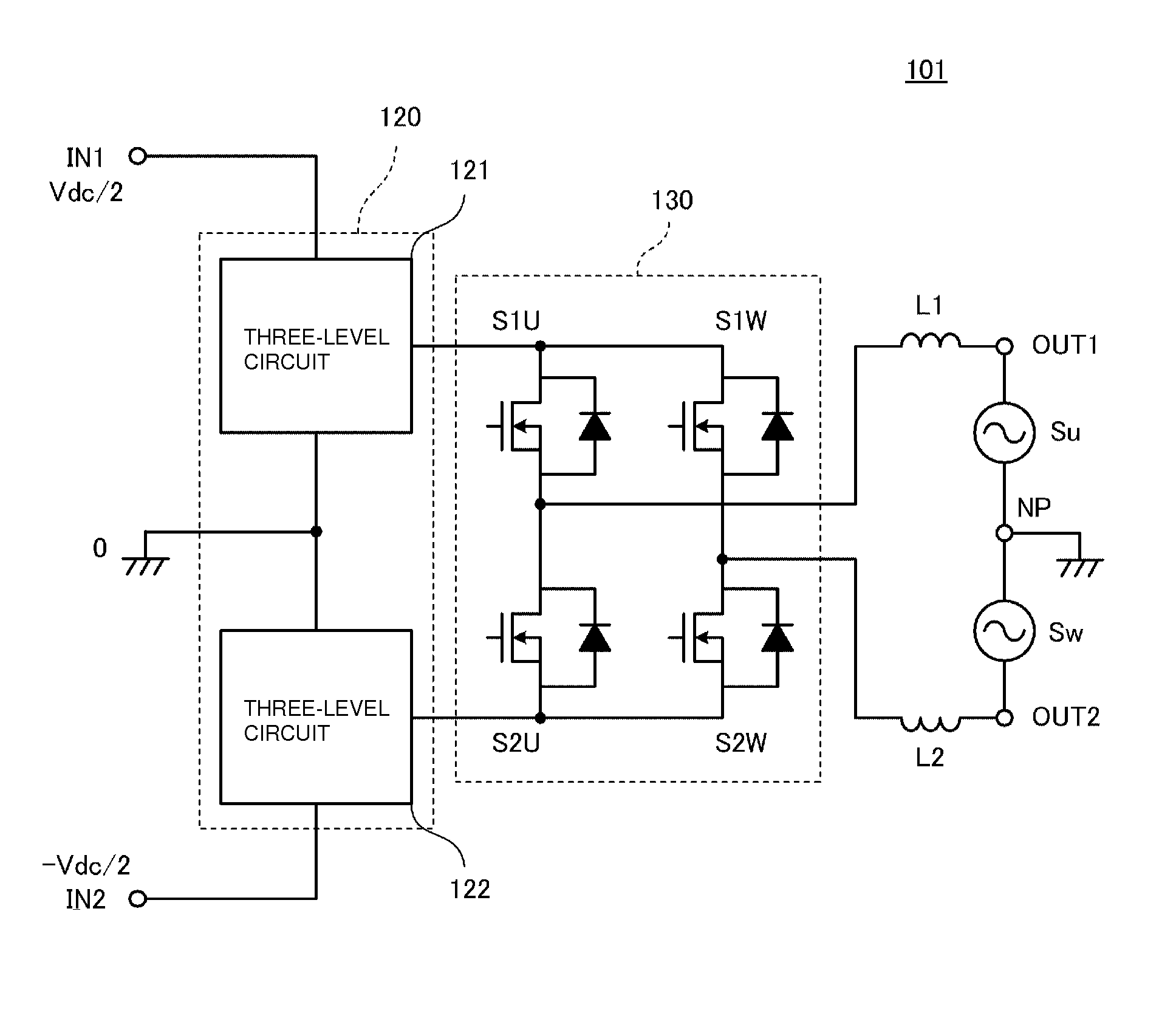
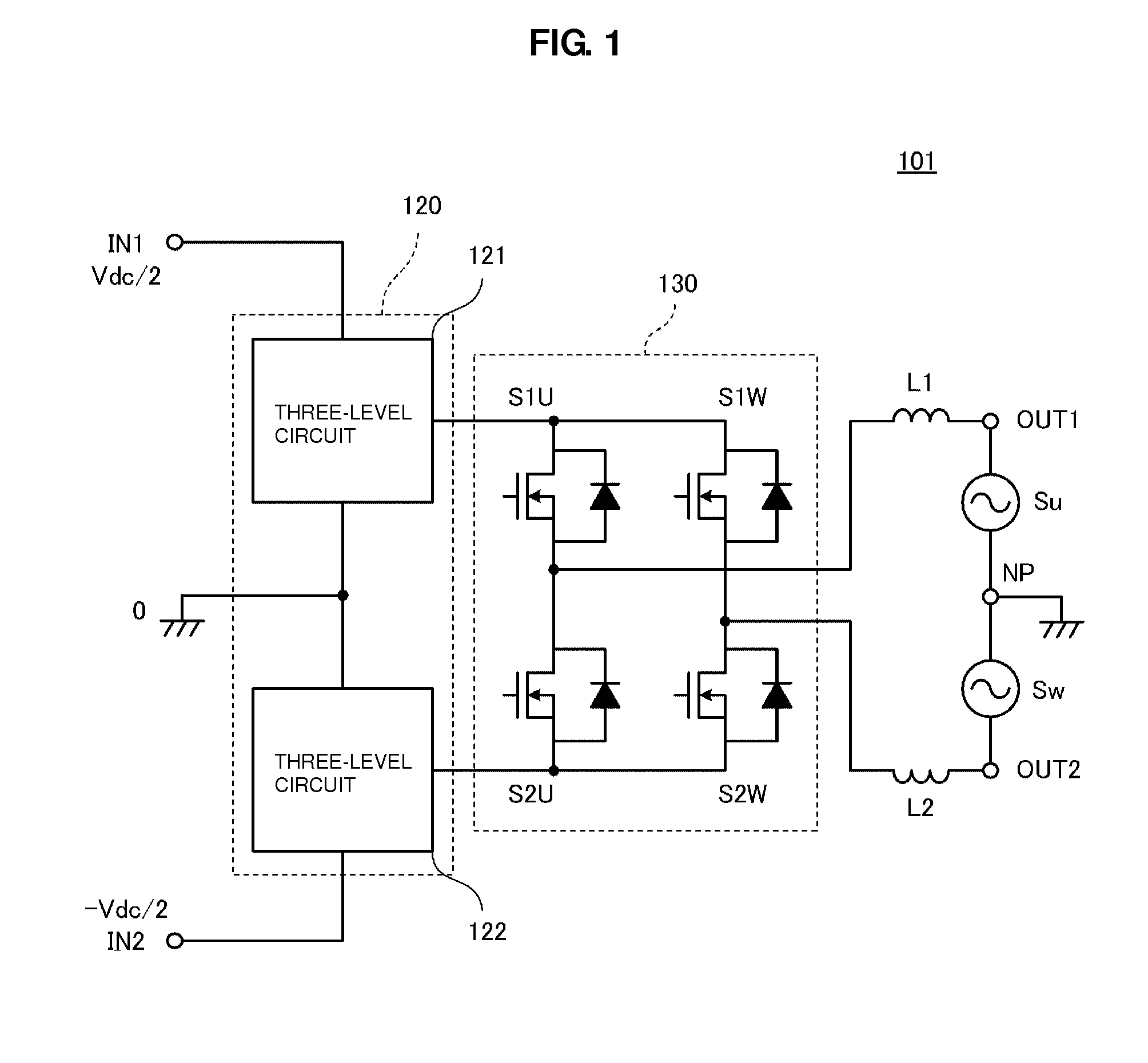
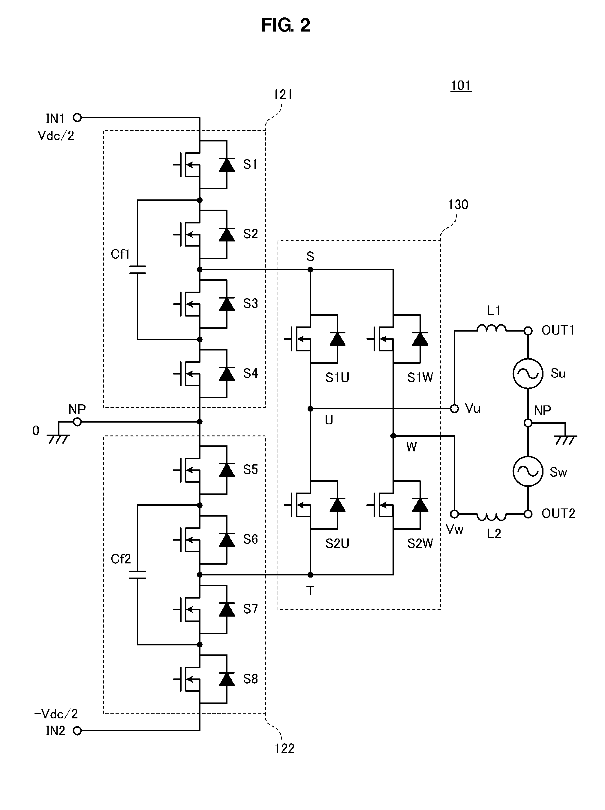
[0042]FIG. 1 is the partially blocked circuit diagram of an inverter device 101 according to a first preferred embodiment of the present invention. The inverter device 101 preferably includes a first input end IN1 and a second input end IN2, into which direct-current power supply voltages are input, and a first output end OUT1 and a second output end OUT2, from which alternating-current voltages are output. Direct-current voltages generated due to, for example, a solar power generation panel are applied to the first input end IN1 and the second input end IN2. In FIG. 1, Su and Sw indicate a single-phase three-wire system having a U-phase and a W-phase. An alternating-current voltage whose effective voltage preferably is about 100 V, for example, is applied between the first output end OUT1 and a neutral point NP, an alternating-current voltage whose effective voltage preferably is about 100 V, for example, is applied between the neutral point NP and the second output end OUT2, and a...
second preferred embodiment
[0070]In the first preferred embodiment, in particular as illustrated in FIGS. 13A to 13D and FIGS. 14A to 14D, an example has been illustrated where the switch elements S1 to S4 in the first three-level circuit 121 and the switch elements S5 to S8 in the second three-level circuit 122 are preferably symmetrically coordinated with each other and are driven. However, the present invention is not limited to a configuration where driving is performed in such a way. In a second preferred embodiment, an example will be illustrated where the switch elements S1 to S4 in the first three-level circuit 121 and the switch elements S5 to S8 in the second three-level circuit 122 preferably are independently driven.
[0071]The circuit configuration of an inverter device in the second preferred embodiment preferably is the same or substantially the same as that illustrated in FIG. 1 and FIG. 2. Accordingly, the symbols illustrated in FIG. 1 and FIG. 2 will be referred to in the following description...
third preferred embodiment
[0074]While, in the first and second preferred embodiments, examples have been illustrated where the positive voltage and the negative voltage preferably are applied to the first input end IN1 and the second input end IN2, respectively, the present invention is not limited to a configuration where two voltages whose polarities are positive and negative are input. In a third preferred embodiment, an example will be illustrated where a direct-current voltage having a single polarity is input.
[0075]FIG. 23 is the circuit diagram of an inverter device 103 according to the third preferred embodiment. This inverter device 103 includes a first input end IN1 and a second input end IN2, into which a direct-current power supply voltage is input, and a first output end OUT1 and a second output end OUT2, from which alternating-current voltages are output. A direct-current voltage generated by, for example, a solar power generation panel, is applied between the first input end IN1 and the second...
PUM
 Abstract
Description
Claims
Application Information
 - R&D
- Intellectual Property
- Life Sciences
- Materials
- Tech Scout
- Unparalleled Data Quality
- Higher Quality Content
- 60% Fewer Hallucinations
Browse by: Latest US Patents, China's latest patents, Technical Efficacy Thesaurus, Application Domain, Technology Topic, Popular Technical Reports.
© 2025 PatSnap. All rights reserved.Legal|Privacy policy|Modern Slavery Act Transparency Statement|Sitemap|About US| Contact US: help@patsnap.com


