
Nozzle repairing method and nuclear reactor vessel

Inactive Publication Date: 2014-03-06
MITSUBISHI HEAVY IND LTD
View PDF4 Cites 3 Cited by
  • Summary
  • Abstract
  • Description
  • Claims
  • Application Information

AI Technical Summary

Benefits of technology

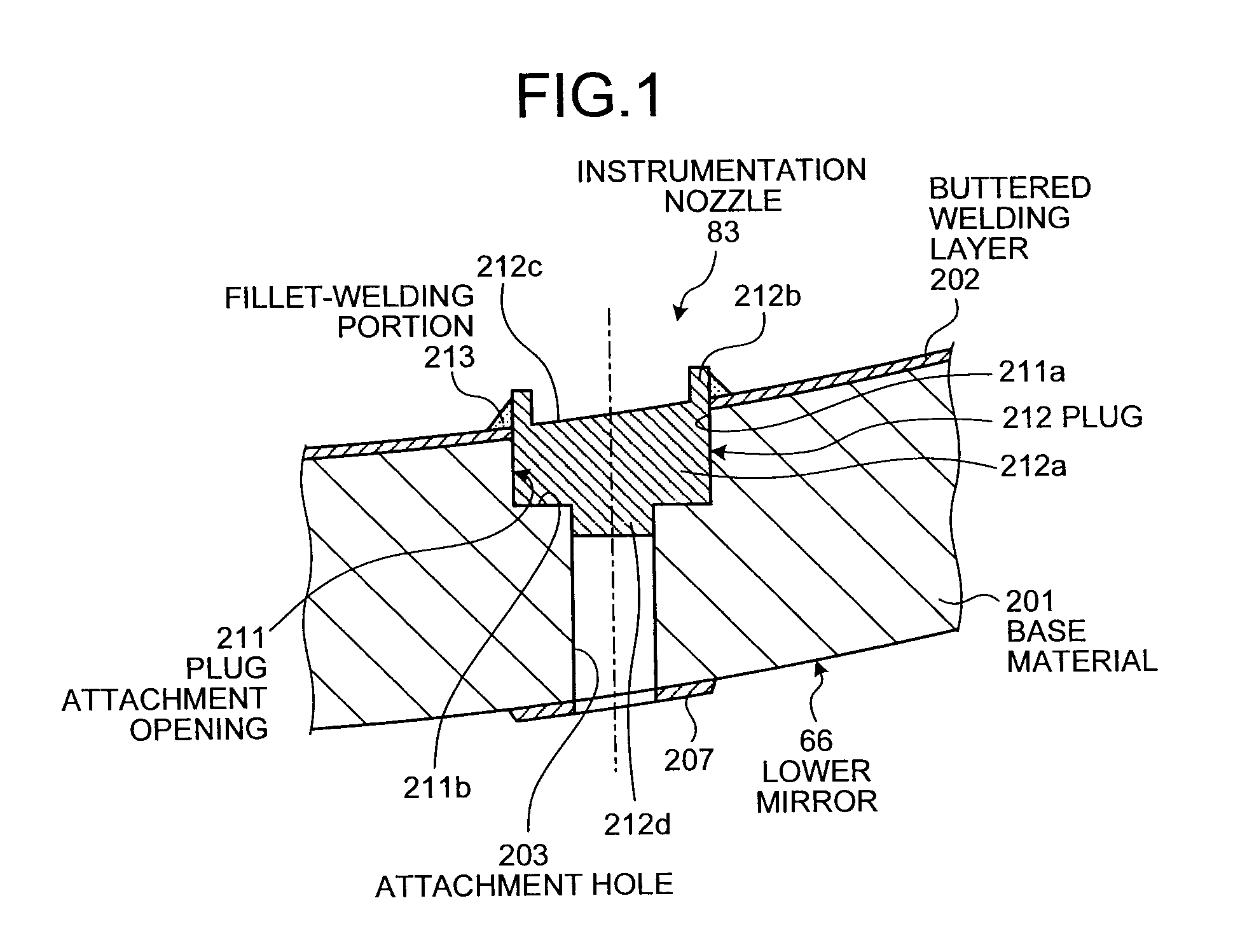
The present invention provides a method for repairing an instrumentation nozzle in a nuclear reactor vessel. The method involves removing a connection portion, in a groove-welding portion, with respect to the in-core instrument tube, removing the in-core instrument tube from the semi-spherical portion of the nuclear reactor vessel, and processing a plug attachment portion for fixing a plug by welding. The invention also includes a nuclear reactor vessel that includes a groove-welding portion for fixing a connection portion between an in-core instrument tube and the vessel, and a plug for plugging any nozzle attachment hole in the instrumentation nozzles. The technical effects of this invention include improving the repair efficiency of the instrumentation nozzle and ensuring the safety of the nuclear reactor vessel during operation.

Problems solved by technology

For this reason, there is a possibility that stress corrosion cracking may be generated in the in-core instrument tube due to the long-time usage, and there is a need to repair the instrumentation nozzle in the event of stress corrosion cracking.
For this reason, the nozzle to be newly attached may be attached with high precision, but the repairing becomes complicated and the repairing cost increases.

Method used


Image

  • Nozzle repairing method and nuclear reactor vessel
  • Nozzle repairing method and nuclear reactor vessel
  • Nozzle repairing method and nuclear reactor vessel

Examples


first embodiment

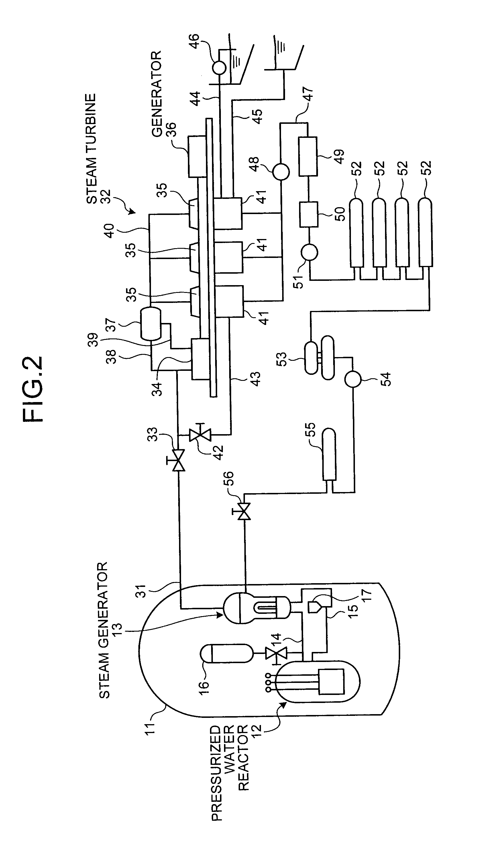
[0038]FIG. 2 is a schematic configuration diagram of a nuclear power plant, and FIG. 3 is a longitudinal sectional view illustrating a pressurized water reactor.

[0039]A nuclear reactor of the embodiment is a pressurized water reactor (PWR) which uses light water as a nuclear reactor coolant and a neutron moderator, adjusts the water to be high-temperature and high-pressure water throughout the entire reactor core so that the light water is not boiled, sends the high-temperature and high-pressure water to a steam generator so as to generate steam by the heat exchange therebetween, and sends the steam to a turbine generator so as to generate electric power.

[0040]In the nuclear power plant with the pressurized water reactor of the embodiment, as illustrated in FIG. 2, a containment 11 accommodates a pressurized water reactor 12 and a steam generator 13, where the pressurized water reactor 12 and the steam generator 13 are connected to each other through a high temperature side feeding ...

second embodiment

[0087]FIG. 19 is a flowchart illustrating a nozzle repairing method according to a second embodiment of the invention, FIG. 20 is a schematic diagram illustrating an operation of removing the upper reactor core internal structure from the nuclear reactor vessel, FIG. 21 is a schematic diagram illustrating a thimble tube cutting operation, FIG. 22 is a schematic diagram illustrating an operation of suspending the lower reactor core internal structure from the nuclear reactor vessel, FIG. 23 is a schematic diagram illustrating an operation of installing the thimble stand in the nuclear reactor vessel, and FIG. 24 is a schematic diagram illustrating a thimble tube supporting operation.

[0088]As in the first embodiment, the nozzle repairing method of the second embodiment includes removing the connection portion with respect to the in-core instrument tube in the groove-welding portion, removing the in-core instrument tube from the lower mirror 66, removing the groove-welding portion and ...


PUM

PropertyMeasurementUnit
Corrosion resistanceaaaaaaaaaa

Abstract

The repairing method includes removing a connection portion with respect to an in-core instrument tube in a groove-welding portion, removing the in-core instrument tube from a lower mirror, removing the groove-welding portion and processing a plug attachment opening, and fixing a plug to the plug attachment opening by welding.

Description

CROSS-REFERENCE TO RELATED APPLICATIONS[0001]This application is based upon and claims the benefit of priority from Japanese Patent Application No. 2012-190394 filed Aug. 30, 2012, the entire contents of which are incorporated herein by reference.BACKGROUND OF THE INVENTION[0002]1. Field of the Invention[0003]The present invention relates to a nozzle repairing method of repairing a nozzle provided in a nuclear reactor vessel and a nuclear reactor vessel provided with a nozzle.[0004]2. Description of the Related Art[0005]For example, a nuclear power plant with a pressurized water reactor (PWR) uses light water as nuclear reactor coolant and neutron moderator, keeps the light water as high-temperature and high-pressure water that is not boiled in the entire reactor core, sends the high-temperature and high-pressure water to a steam generator so as to generate steam by a heat exchange therebetween, and sends the steam to a turbine generator so as to generate electric power.[0006]In suc...

Claims


Application Information

Patent Timeline
IPC IPC(8): B23K31/02G21C5/00
CPCG21C19/207B23K2201/06G21C13/036G21C17/017G21C13/02F16L5/022B23K2201/001B23K31/027Y02E30/40B23P6/00G21C5/00B23K2203/02B23K31/02B23K2201/12B23K2101/001B23K2101/12B23K2103/02Y02E30/30
Inventor YAMAMOTO, TAKESHIHAMAMOTO, TOMOCHIKAHORI, NOBUYUKINISHIMURA, TSUYOSHISAKASHITA, HIDESHI
Owner MITSUBISHI HEAVY IND LTD
Learn More