Adhesive Bone Conduction Hearing Device

a bone conduction and hearing device technology, applied in the direction of hearing aid mounting/interconnection, deaf-aid sets, stereophonic arrangments, etc., can solve the problems of unsuitable pressure points, unsuitable pressure points, and unsuitable devices disclosed, so as to avoid unsuitable pressure points

Active Publication Date: 2014-03-06
SOPHONO
View PDF2 Cites 91 Cited by
  • Summary
  • Abstract
  • Description
  • Claims
  • Application Information

AI Technical Summary

Benefits of technology

[0041]One of the advantages of the instant technology is the ability to generate a suitable normal force without the need for undesirable components that can be uncomfortable, obtrusive, or overly intrusive. Accordingly, one embodiment of the invention is any of the bone conduction hearing devices or method of exerting a normal force that is abutment-free, headband-free or both. Headband-free is used broadly to refer to and component that spans a significant circumference of the user skull that secures the device to the head, and can include spectacles, head-sets and soft-bands.
[0042]In an embodiment, any of the hearing devices provided herein, and methods related thereto, relate to the external component portion that contacts the user that is configured and shaped to fit against skin overlying the skull of the user, including configured to ensure unwanted pressure points are avoided. In an aspect, the inner surface of the external component is in conformal contact with the skin overlying the skull of the user. In this embodiment, the shaping helps contour the external component inner-facing surface to the shape of the skull, thereby providing conformal contact between the inner-facing surface and the underlying user surface.

Problems solved by technology

The various devices disclosed in the art, however, have substantial limitations in that they either do not sufficiently and reliably provide adequate force, provide too much force, are obtrusive or uncomfortable, or require implantation with attendant costs and surgical intervention.

Method used


Image

  • Adhesive Bone Conduction Hearing Device
  • Adhesive Bone Conduction Hearing Device
  • Adhesive Bone Conduction Hearing Device

Examples


example 1

Headbands

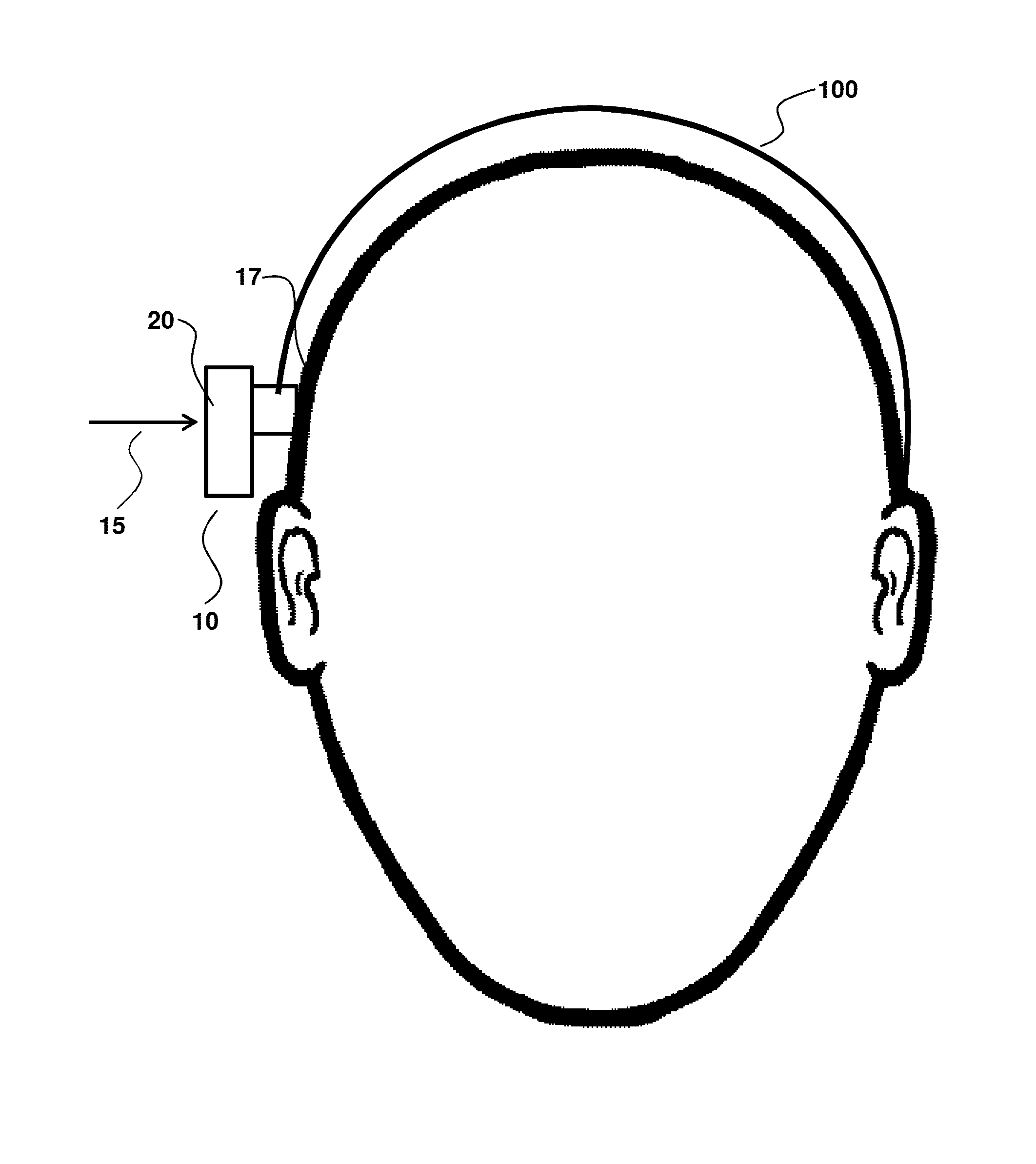
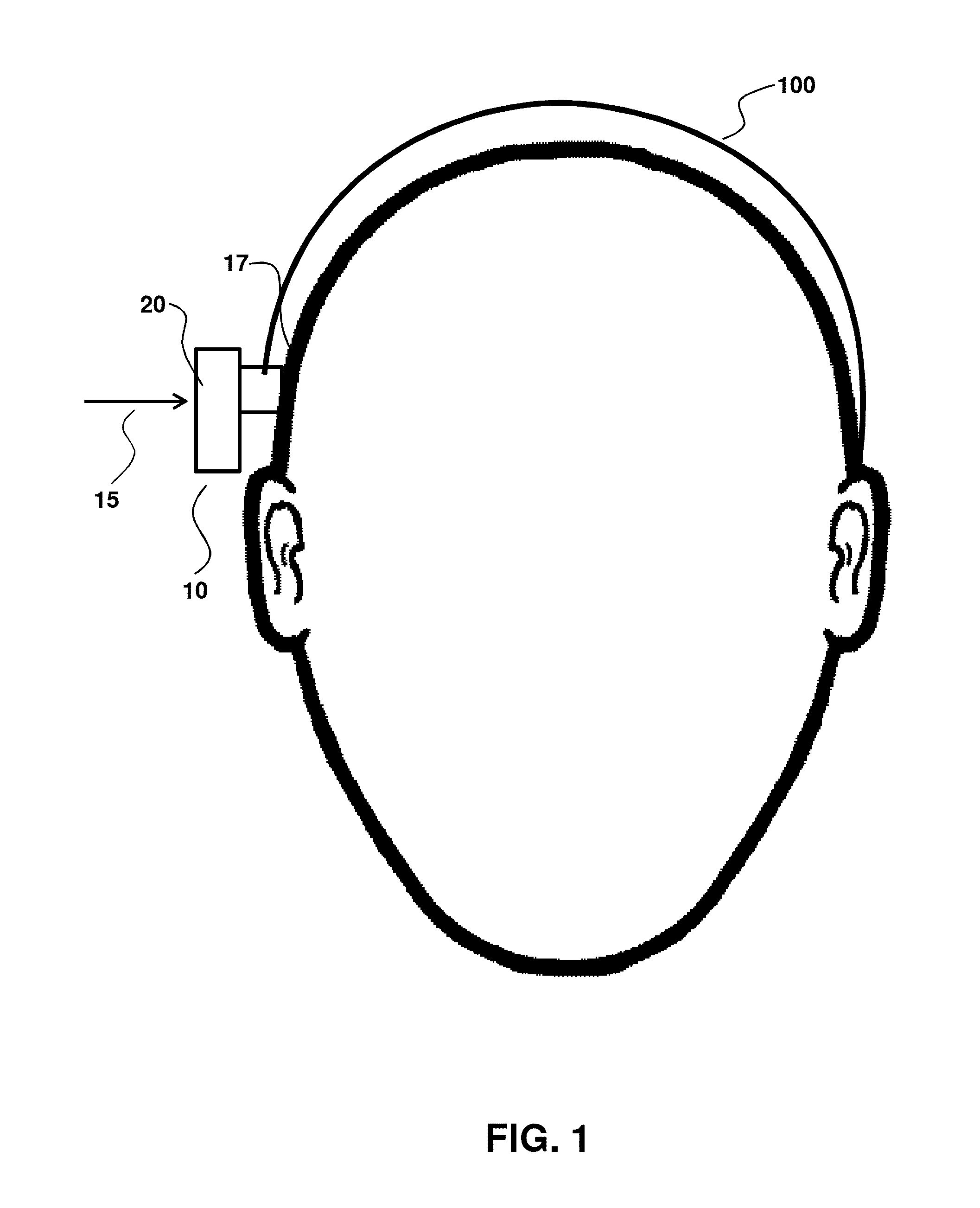
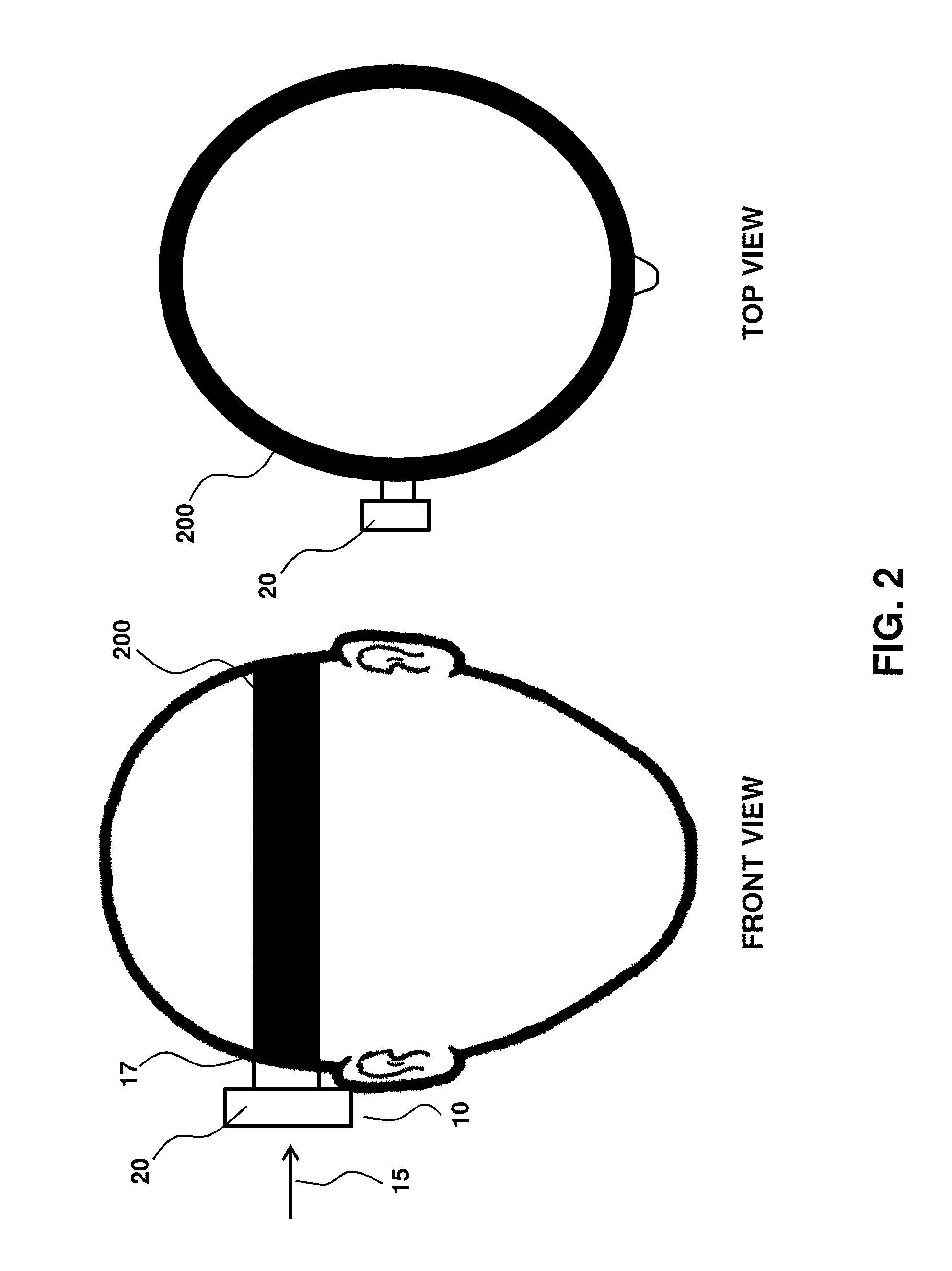
[0065]FIGS. 1-2 illustrate an embodiment where a headband 100 (FIG. 1) or a softband 200 (FIG. 2) provide a normal force 15 that secures an external component 20 of a hearing device 10 to a user surface 17. This example suffers a number of disadvantages, such as the band 100 or 200 being uncomfortable, unsightly and unreliable during use, particularly as to providing a well-defined and controlled normal force. Accordingly, an aspect of the invention relates to an adhesive anchor that is not a headband, softband or any other band that transits around the head.

example 2

Magnets

[0066]FIG. 3 illustrates an embodiment where magnets provide a normal force to secure an external component 20 to a user surface 17. In this embodiment, the magnets include internal magnets 300 and external magnets 310 secured within magnet spacer 311, relative to user surface 17 that corresponds to skin 18 overlying the skull 19. In this aspect, the magnets 300 and 310 may be considered to form an adhesive anchor that is partially removable in that upon removal of the external component the internal magnets 300 remain implanted in the user. In an aspect, the magnet spacer 311 has an inner surface 312 shaped for conformal contact with the skin 18 overlying the skull 19.

example 3

Adhesives

[0067]FIG. 4 describes the simplest form of an adhesive anchor 400 that secures the external component 20 to the user surface 17. In an embodiment, the adhesive anchor is an adhesive material having a first and a second surface that is sticky, so that the first end sticks to the user surface 17 and the second surface to the external component 20. A drawback with this embodiment is that the generated normal force 15 is often too low to provide good vibration transmission. This is indicated by the short length of the normal force arrow 15.

[0068]FIGS. 7-10 illustrate an embodiment where a self-adhesive anchor, such as an adhesive layer, generates a sufficient normal force to transmit vibration to the skull while maintaining reliability and comfort, including over use on the time frame of a day or more. FIG. 7 illustrates an adhesive anchor 700 that may be used, for example, in an adult. FIG. 7A is a perspective view of a fully assembled self-adhesive anchor 700 with a top adhe...


PUM


Abstract

Provided are bone conducting hearing devices having a normal force that secures the device to a user. A removable adhesive anchor secures an external component of the bone conducting hearing device to the user and provides reliable connecting that is comfortable, such as by a substantially uniform force generation over the contact area between the device and the user. Because the adhesive anchor is removable, a user can readily and reliably remove the device or connect the device, as desired. Also provide are methods of connecting any of the bone conducting hearing devices provided herein to a user, including the mastoid process of the user.

Description

CROSS-REFERENCE TO RELATED APPLICATIONS[0001]This application claims benefit of provisional patent application 61 / 697,427 filed Sep. 6, 2012, which is hereby incorporated by reference to the extent it is not inconsistent with the present disclosureBACKGROUND OF THE INVENTION[0002]Provided herein are bone conduction hearing devices having a specially configured mechanism for securing the device to the side of the head.[0003]Bone conduction hearing devices are a significant and important market in the field of hearing devices or hearing aids. There are five major types of bone conduction devices, including: (1) External bone conduction devices where a vibrator is held to the side of the head by a band that traverses around the head (e.g., U.S. Pat. No. 7,822,215); (2) Bone anchored hearing devices where a screw is placed through the skin into the skull and a vibrator transducer is hung to the side of the screw (see, e.g., BAHA® hearing aid by Cochlear Corp.); (3) Magnetic bone conduct...

Claims


Application Information

Patent Timeline
Patent Type & Authority Applications(United States)
IPC IPC(8): H04R25/00
CPCH04R5/0335H04R2460/13H04R25/60
Inventor KASIC, II, JAMES, F
Owner SOPHONO
Why Eureka
Try Eureka