
Image formation apparatus

a technology of image formation apparatus and induction heating device, which is applied in the direction of electric/magnetic/electromagnetic heating, electrographic process, instruments, etc., can solve the problems of increasing switching loss, noise production, and breakage of switching elements

Active Publication Date: 2014-03-06
KONICA MINOLTA INC
View PDF8 Cites 8 Cited by
  • Summary
  • Abstract
  • Description
  • Claims
  • Application Information

AI Technical Summary

Benefits of technology

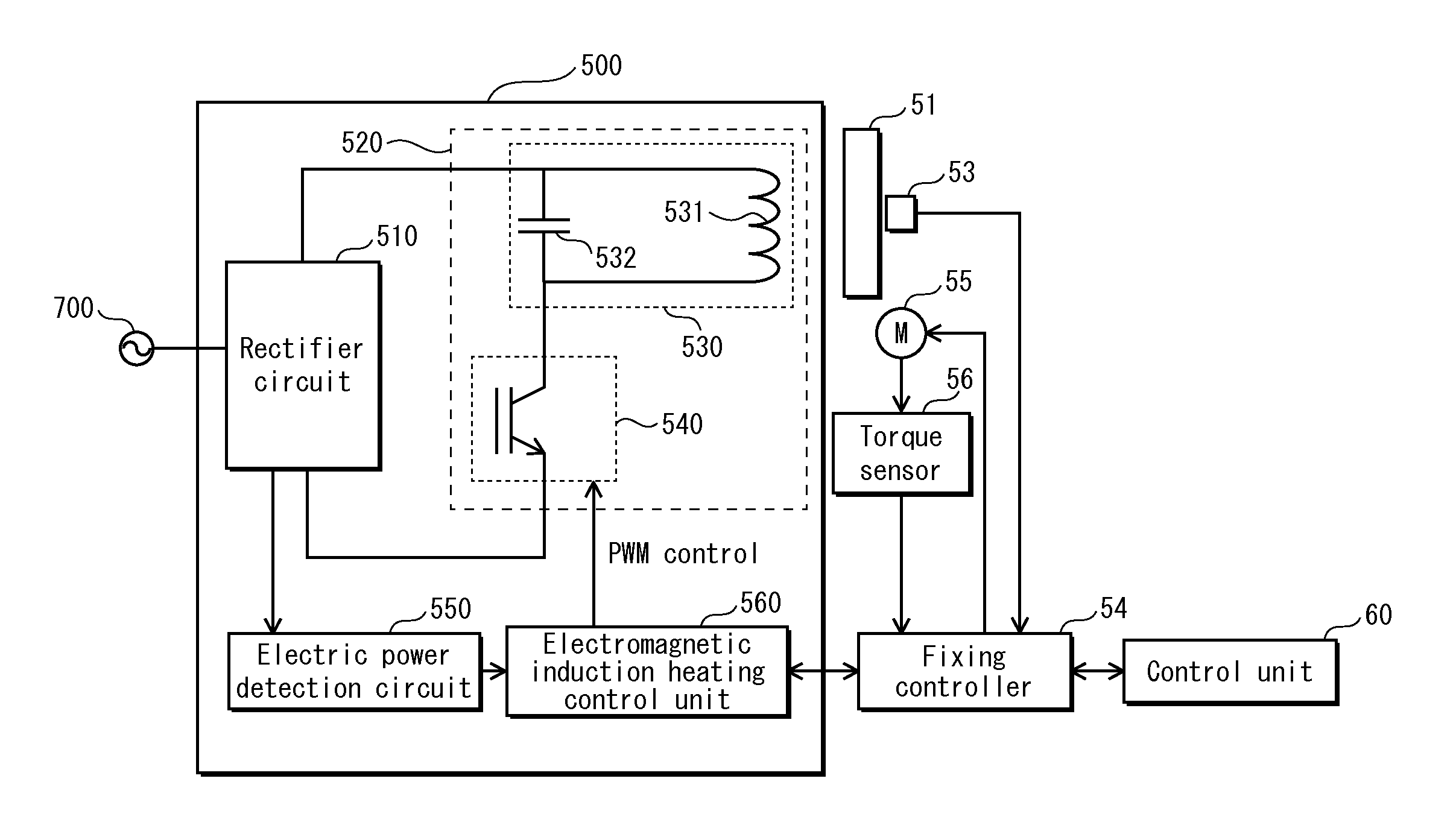
The present invention provides an electromagnetic induction heating apparatus that uses a resonance circuit with an inductor and capacitor. This apparatus includes a direct-current electric power supply and a switching element for controlling the electric power supplied to the resonance circuit. A switching control unit performs intermittent control of the electric power supplied to the resonance circuit by controlling the ON and OFF switching of the switching element. The intermittent control is performed with gradual control, where the electric power supplied to the resonance circuit increases gradually when the ON and OFF switching is initiated, and it decreases gradually until stopping. This gradual control with fewer steps provides efficient heating without sudden power increases or decreases.

Problems solved by technology

Thus, when the switching element is switched ON and OFF with timing on the order of microseconds, switching loss occurs every time the switching element is switched ON, which produces increasing switching loss and is likely to cause breakage of the switching element through the production of heat that accompanies switching loss.
Thus, the component subject to heating (i.e., the fixing roller) is repeatedly deformed, which results in a problem of noise production.
However, although this approach does prevent the occurrence of noise, a further problem occurs in that the switching loss is increased.

Method used


Image

  • Image formation apparatus
  • Image formation apparatus
  • Image formation apparatus

Examples


Embodiment Construction

[0030]The following describes an electromagnetic induction heating device according to a preferred Embodiment of the present invention, using an example of application to a tandem colour digital printer (hereinafter simply termed a printer).

[1] Printer Configuration

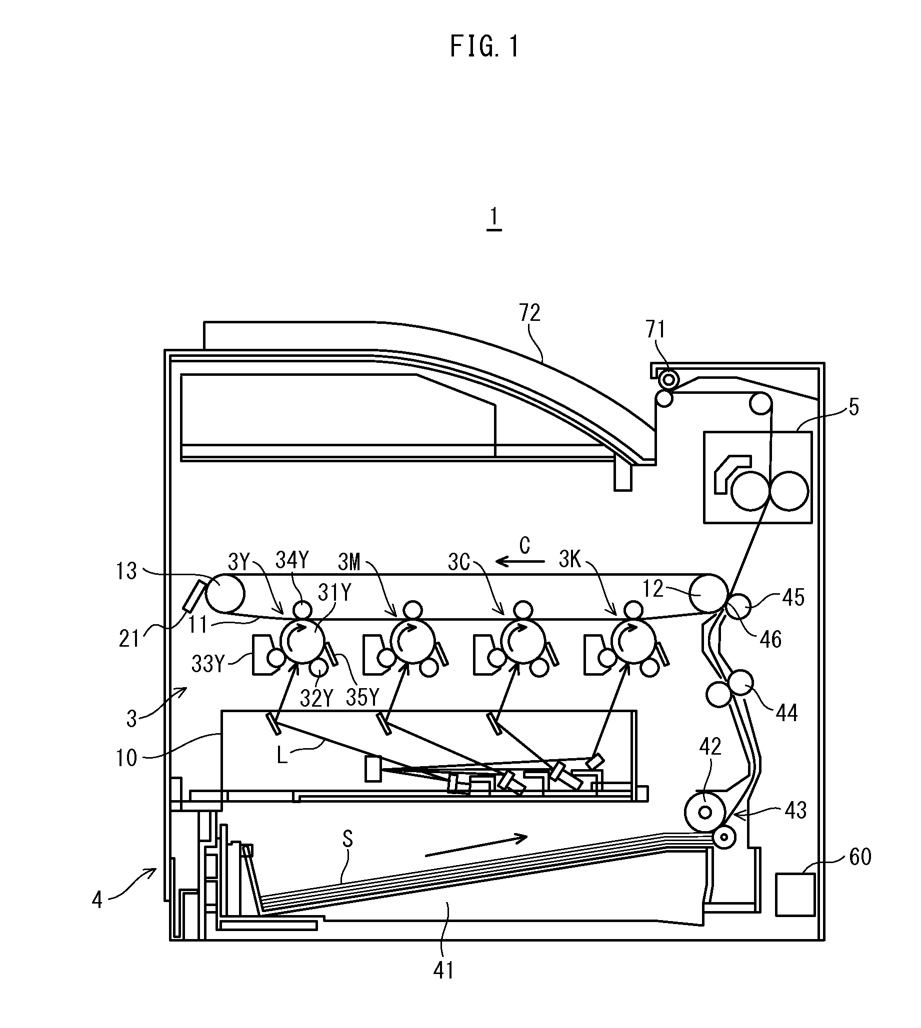
[0031]First, the configuration of a printer pertaining to the present Embodiment is described. FIG. 1 illustrates the configuration of the printer pertaining to the present Embodiment. As shown, a printer 1 includes an image processing unit 3, a take-up unit 4, a fixing device 3, and a control unit 60.

[0032]The printer 1 is connected to a network (e.g., a LAN), receives a print instruction from a (non-diagrammed) external terminal device or from a non-diagrammed operation panel having a display, forms a toner image corresponding to the received instruction in each of yellow, magenta, cyan, and black, then creates a full-colour image on a recording sheet through overlay transfer of these images, thus executing a print proc...


PUM


Abstract

An electromagnetic induction heating apparatus comprises: a resonance circuit that includes a inductor and a capacitor; a direct-current electric power supply; and a switching element performing ON and OFF switching of electric power supplied to the resonance circuit by the direct-current electric power supply; performs intermittent control of the electric power supply by controlling the ON and OFF switching at regular intervals, and by performing control to stop the electric power supply when not controlling the ON and OFF switching, wherein during the intermittent control, the switching control unit performs gradual control such that, upon beginning the control of the ON and OFF switching, the electric power supply gradually increases to reach a target value, and upon stopping the control of the ON and OFF switching, the electric power supply gradually decreases from the target value until stopping, such that the gradual decrease involves fewer steps than the gradual increase.

Description

[0001]This application is based on application No. 2012-193352 filed in Japan, the contents of which are hereby incorporated by reference.BACKGROUND OF THE INVENTION[0002](1) Field of the Invention[0003]The present invention relates to an electromagnetic induction heating device that controls electric power supplied to a resonance circuit that is connected to a switching element by performing control of ON and OFF switching by a switching element, and has an inductor and a capacitor, and that performs electromagnetic induction of heating a component subject to heating through electromagnetic flux in the inductor. In particular, the present invention pertains to technology for preventing the occurrence of noise produced when the electromagnetic induction heating device performs intermittent control of switching the switching element ON and OFF when low electric power is supplied, which is likely to cause switching loss.[0004](2) Description of the Related Art[0005]Electromagnetic ind...

Claims


Application Information

Patent Timeline
IPC IPC(8): G03G15/20H05B6/06
CPCG03G15/2039H05B6/06G03G15/205G03G15/80
Inventor KIRIKUBO, SEIICHIGOTO, MASAAKIYAMAMOTO, YUTAKATSUJIMOTO, TAKAHIROWATANABE, HIROYUKIMINE, HIDENORIISHII, MASATO
Owner KONICA MINOLTA INC
Learn More