
Fuel cell system activation method and fuel cell system

Active Publication Date: 2014-03-06
HONDA MOTOR CO LTD
View PDF11 Cites 11 Cited by
  • Summary
  • Abstract
  • Description
  • Claims
  • Application Information

AI Technical Summary

Benefits of technology

The present invention provides a method and system for activating a fuel cell while preventing deterioration of the fuel cell during activation. The control device is able to achieve this by appropriately increasing the electric voltage while maintaining the desired concentration of anode gas.

Problems solved by technology

As a result, there is a possibility that it may become impossible to avoid the cathode from being at a high potential (for example, the cathode potential being 0.9V or higher), and consequently the fuel cell stack may become deteriorated.
Furthermore, according to the method for starting a fuel cell system of the conventional technique above, there is a possibility that the fuel cell stack may become deteriorated if electric power generation is performed in a state where the hydrogen concentration is lower than a desired concentration, that is, for example, where the anode and cathode of the fuel cell stack are charged with air.

Method used


Image

  • Fuel cell system activation method and fuel cell system
  • Fuel cell system activation method and fuel cell system
  • Fuel cell system activation method and fuel cell system

Examples


Embodiment Construction

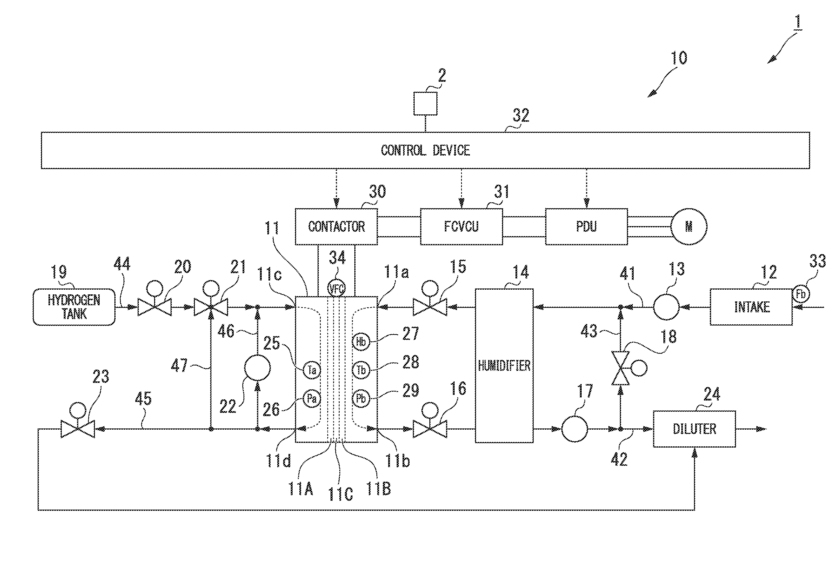
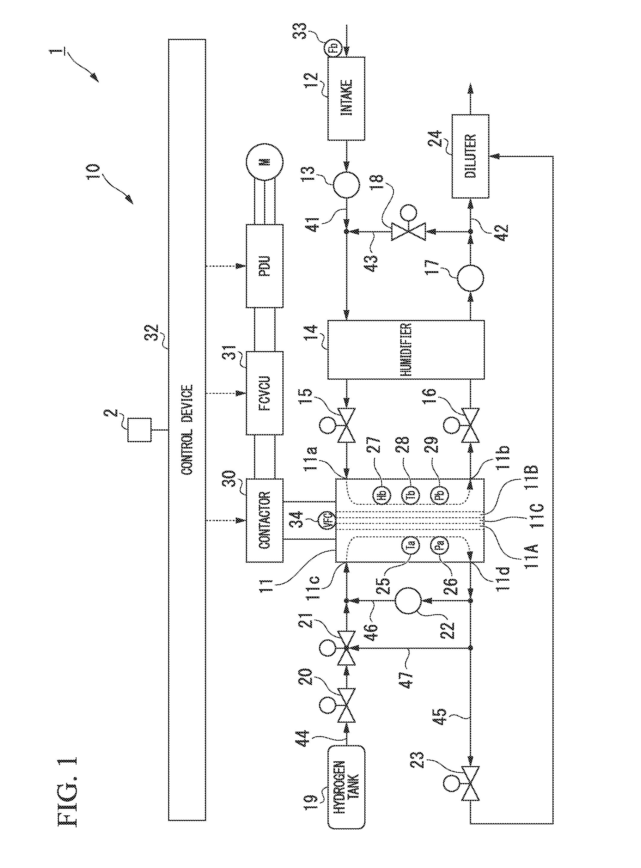
[0064]Hereunder, a fuel cell system and a fuel cell system activation method according to an embodiment of the present invention are described, with reference to the accompanying drawings.

[0065]A fuel cell system 10 of the present embodiment is mounted as a power supply, for example, on a vehicle 1 that is provided with a propulsion motor (M) and a power drive unit (PDU) that controls the motor (M).

[0066]The vehicle 1 is provided with a switch 2, such as an ignition switch, that outputs a signal for instructing an activation of the vehicle 1 according to an input operation or the like performed by a driver.

[0067]For example, as shown in FIG. 1, the fuel cell system 10 comprises: a fuel cell stack 11 (fuel cell); an intake 12; an air pump 13 (cathode gas supplying device); a humidifier 14; a sealing inlet valve 15 (cathode gas supplying device, sealing valve); a sealing outlet valve 16 (cathode gas supplying device, sealing valve); a pressure control valve 17; a bypass valve 18; a hy...


PUM


Abstract

As an activation time power generation mode of a fuel cell system, a control device executes: a first step of determining whether or not hydrogen is present in an anode gas flow path; a second step of bringing a contactor to a connected state if hydrogen is detected in the first step as being present in the anode gas flow path; a third step of supplying air to a cathode through a cathode gas flow path after the second step has been executed; and a fourth step of, if a voltage of the fuel cell stack detected by a voltage detection device reaches a predetermined voltage, connecting an electrical load to the fuel cell stack, and performing electric power generation of the fuel cell stack while maintaining the voltage at or below the predetermined voltage.

Description

CROSS-REFERENCE TO RELATED APPLICATION[0001]Priority is claimed on Japanese Patent Application No. 2012-187746, filed Aug. 28, 2012, the contents of which are incorporated herein by reference.BACKGROUND[0002]1. Technical Field[0003]The present invention relates to a fuel cell system activation method and a fuel cell system.[0004]2. Background Art[0005]Heretofore, there has been known a starting method in which at the time of activating a fuel cell stack, air is not supplied to a cathode when supplying hydrogen continuously to an anode to replace (purge) air that is present at the anode with hydrogen, and after completion of the activation accompanied by this replacement (purge), air supply to the cathode is started while an electrical load is connected to the fuel cell stack, to thereby generate electric power (for example, refer to Japanese Patent No. 4357836).[0006]Moreover, heretofore, there has been known a method for starting a fuel cell system from a state where an anode and a...

Claims


Application Information

Patent Timeline
IPC IPC(8): H01M8/04
CPCH01M8/04552H01M8/04223H01M8/04388H01M8/04559H01M8/04753H01M2250/20B60L58/31Y02T90/40Y02E60/50H01M8/04302H01M8/04225H01M8/2457
Inventor FURUSAWA, KOICHIRONAKAJIMA, NOBUTAKAYAMAZAKI, KAORU
Owner HONDA MOTOR CO LTD
Learn More