Stereoscopic System for Minimally Invasive Surgery Visualization

Inactive Publication Date: 2014-03-06
VANTAGE SURGICAL SYST
View PDF23 Cites 166 Cited by
  • Summary
  • Abstract
  • Description
  • Claims
  • Application Information

AI Technical Summary

Benefits of technology

[0007]In some aspects of the disclosure one or more of these problems are addressed by returning control of a stereoscopic video camera to the surgeon via a novel steering frame. The stereoscopic video camera can be able to obtain stereoscopic images via a single objective lens thus allowing for more light and higher spatial resolution. In some e

Problems solved by technology

Digital zoom is also an option; however, this approach suffers from reduced pixel resolution.
Furthermore, compared to ope

Method used


Image

  • Stereoscopic System for Minimally Invasive Surgery Visualization
  • Stereoscopic System for Minimally Invasive Surgery Visualization
  • Stereoscopic System for Minimally Invasive Surgery Visualization

Examples


Example

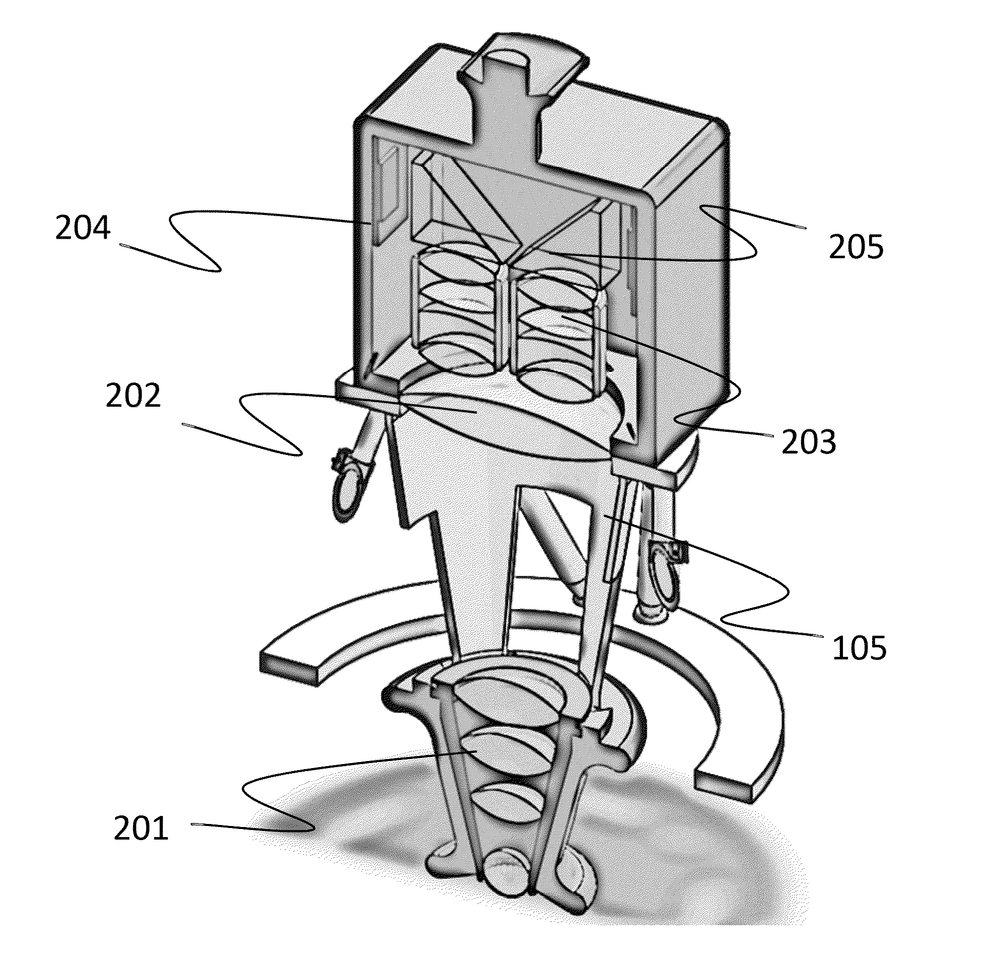
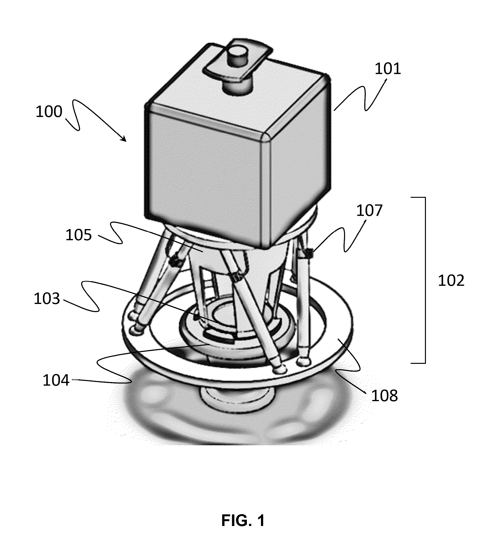
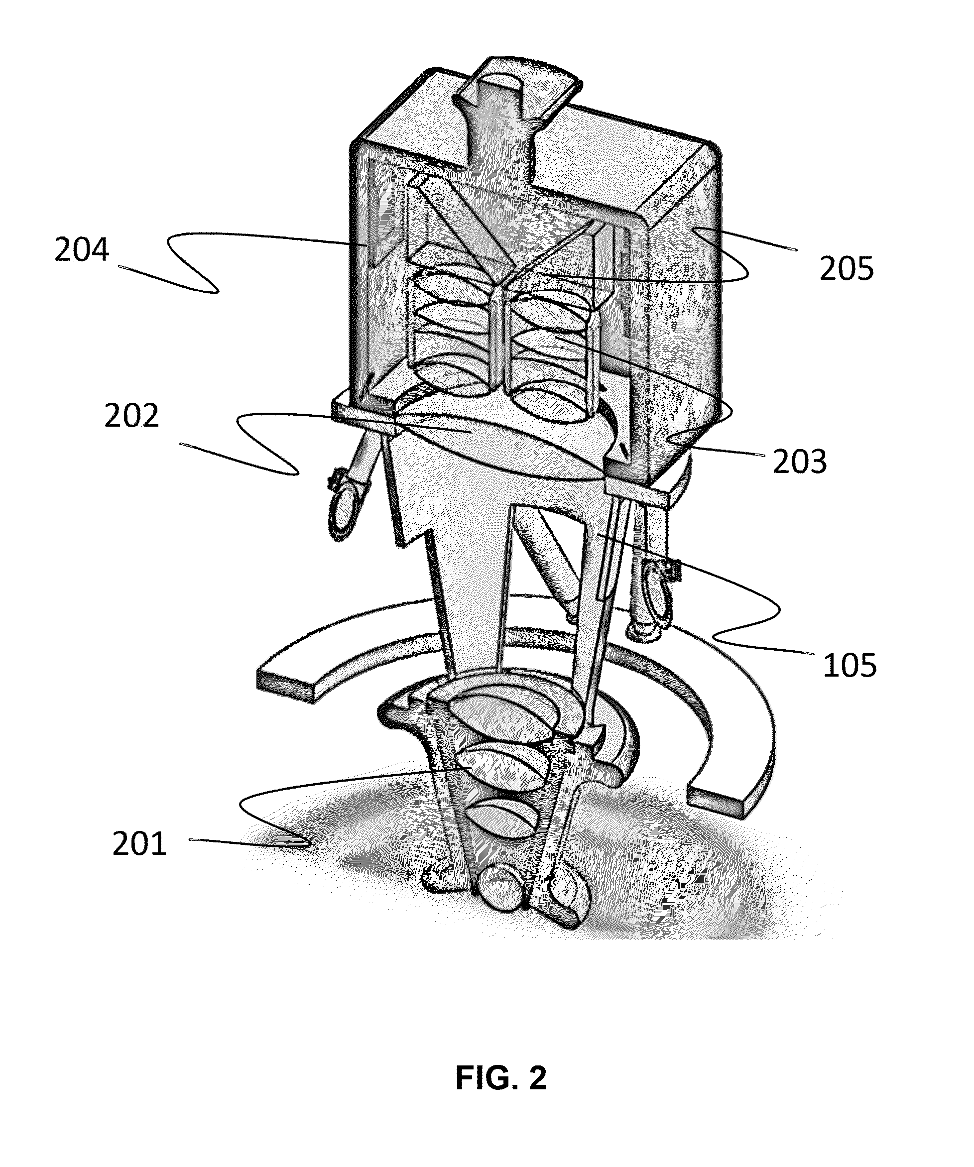
[0040]The disclosure will now be described with reference to the drawing figures, in which like reference numbers refer to like parts throughout. Various aspects of the invention may be illustrated by components that are coupled, sealed, attached, and / or joined together. As used herein, the terms “coupled”, “sealed”, “attached”, and / or “joined” are used to indicate either a direct connection between two components or, where appropriate, an indirect connection to one another through intervening or intermediate components. In contrast, when a component is referred to as being “directly coupled”, “directly sealed”, “directly attached”, and / or “directly joined” to another component, there are no intervening elements present.

[0041]Relative terms such as “lower” or “bottom” and “upper” or “top” may be used herein to describe one element's relationship to another element illustrated in the drawings. It will be understood that relative terms are intended to encompass different orientations ...


PUM


Abstract

Embodiments of the present invention provide improved visualization systems and methods for minimally invasive surgery. Some embodiments include the use of reverse kinematic positioning of camera systems to provide rapid and manual surgeon controllable positioning of camera systems as well as display of 3D surgical area images along the line of sight between a surgeon's eyes and the surgical area itself.

Description

RELATED APPLICATIONS[0001]This application claims benefit of U.S. Provisional Patent Application No. 61 / 693,551 filed Aug. 27, 2012, and is a Continuation in Part of U.S. Non-Provisional Patent Application No. 13 / 761,136 filed Feb. 6, 2013 which claims priority to U.S. Provisional Patent Application 61 / 595,467 filed Feb. 6, 2012. Each of these referenced applications is incorporated herein by reference as if set forth in full herein.FIELD OF THE INVENTION[0002]The present invention relates generally to the field of minimally invasive surgery (MIS) and more particularly to improved visualization methods and tools for use in such surgical procedures.BACKGROUND OF THE INVENTION[0003]During minimally invasive surgical procedures it is common for hand held endoscopes to be used for visualization where images captured by these endoscopes are displayed on monitors that are placed away from the surgical field.[0004]In this configuration the surgeon has given up control to an assistant (assi...

Claims


Application Information

Patent Timeline
IPC IPC(8): A61B19/00A61B1/313A61B17/00A61B1/00A61B1/04
CPCA61B19/5225A61B1/00154A61B1/04A61B1/00009A61B1/00045A61B1/00188A61B1/00193A61B1/3132A61B1/00128A61B1/00039A61B17/00234A61B2017/00221A61B2017/00283A61B1/00048A61B1/00149A61B90/361A61B90/37A61B2090/371A61B1/000094A61B1/00042
Inventor WILSON, JASONARAT, VACITBLUMENKRANZ, DR. MARK
Owner VANTAGE SURGICAL SYST
Why Eureka
Try Eureka