Paperboard corner, and method of manufacturing the same

a paperboard corner and corner technology, applied in the field of paperboard corners and paperboard corner improvement, can solve the problems of not providing the desired rigidity and resistance to tearing, the cost of such paper contributes to the relatively high production cost of such corners, and the drawbacks of such conventional paperboard forms, so as to reduce the manufacturing cost of paperboard protective devices, improve the structural integrity of the form, and improve the effect of the quality of the corner

Active Publication Date: 2014-03-13
ABZAC CANADA INC
View PDF19 Cites 5 Cited by
  • Summary
  • Abstract
  • Description
  • Claims
  • Application Information

AI Technical Summary

Benefits of technology

[0031]The different plies and / or the corner as a whole may be coated with a substance or chemically treated so as to reinforce the structural integrity of the form, and so as to provide some water resistance.
[0032]The paperboard corner and manufacturing process thereof advantageously helps reduce the manufacturing costs of paperboard protective devices, since thinner plies can be used. Using thinner plies helps lower the overall manufacturing costs of the corners, and the wrapping of plies creates a stronger corner compared to conventional corners having a similar overall thickness.

Problems solved by technology

Also known in the art are the substantial drawbacks associated with such conventional paperboard forms.
The type of paper used for some types of conventional corners is generally thick and dense, such as corrugated paperboard, and the cost of such paper contributes to the relatively high production costs for such corners, and especially for thicker corner forms.
For applications in which the corners are to be strapped, the paperboard is selected mainly as a function of its cost and therefore may not provide the desired rigidity and resistance to tearing that is desired when transporting, packaging, or strapping certain merchandise.
Furthermore, the material making up conventional corners is often selected based solely on cost, and there is therefore a wide variance in the type and quality of material used.

Method used


Image

  • Paperboard corner, and method of manufacturing the same
  • Paperboard corner, and method of manufacturing the same
  • Paperboard corner, and method of manufacturing the same

Examples


Embodiment Construction

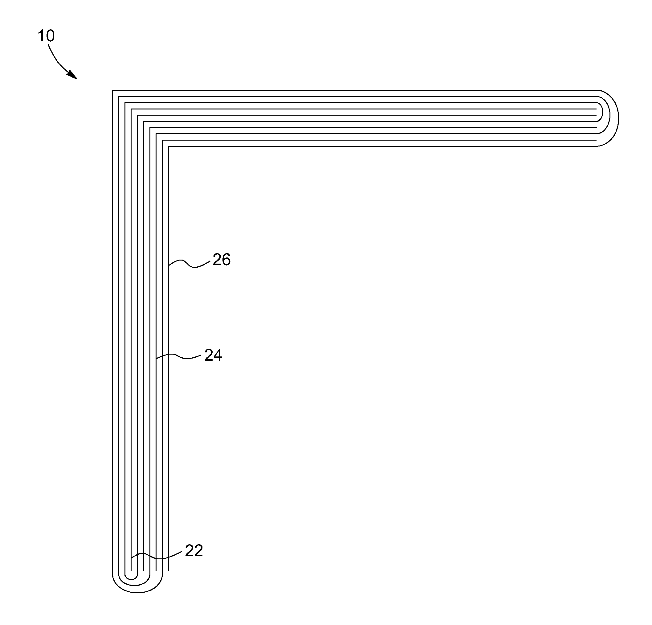
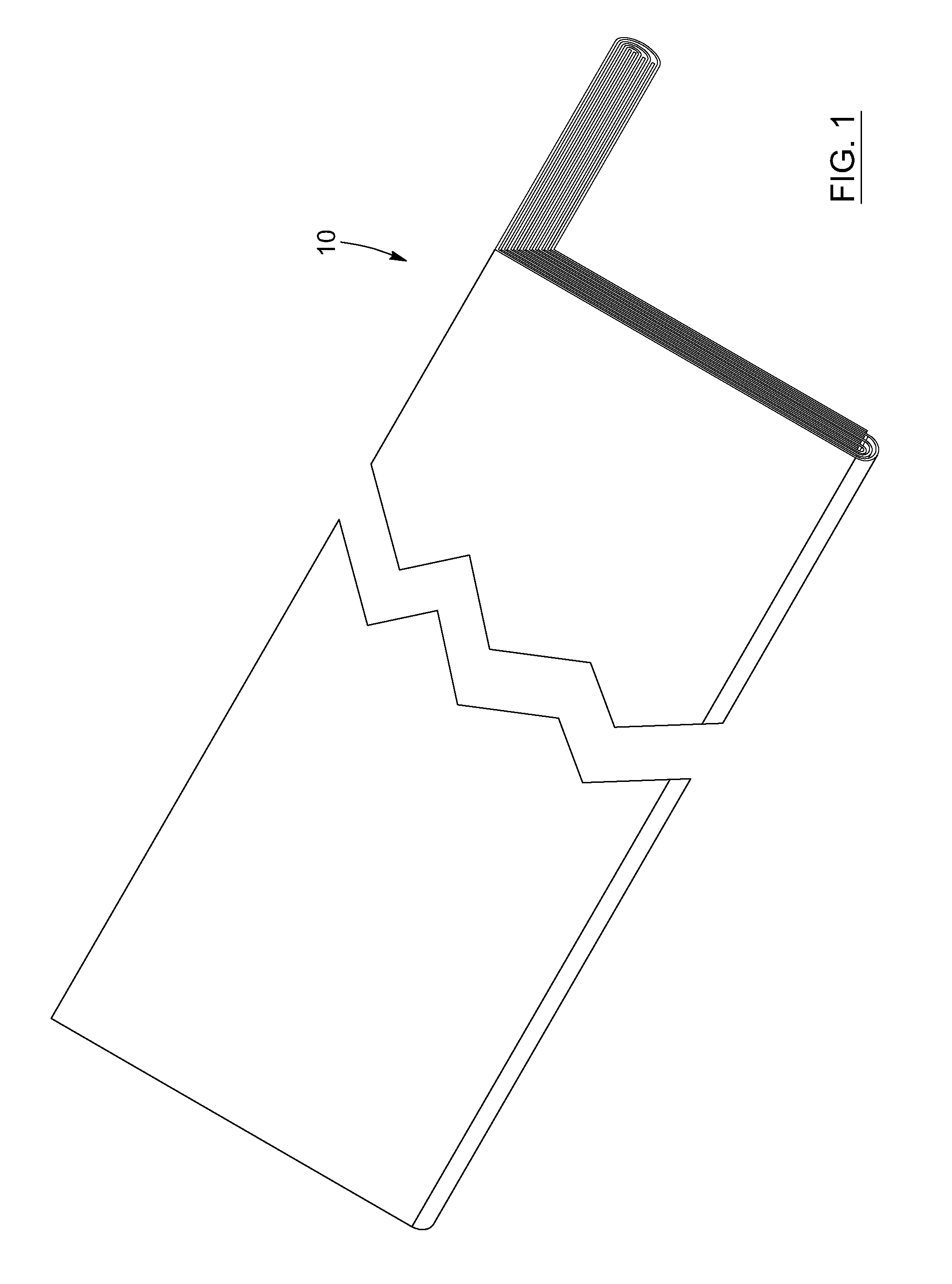
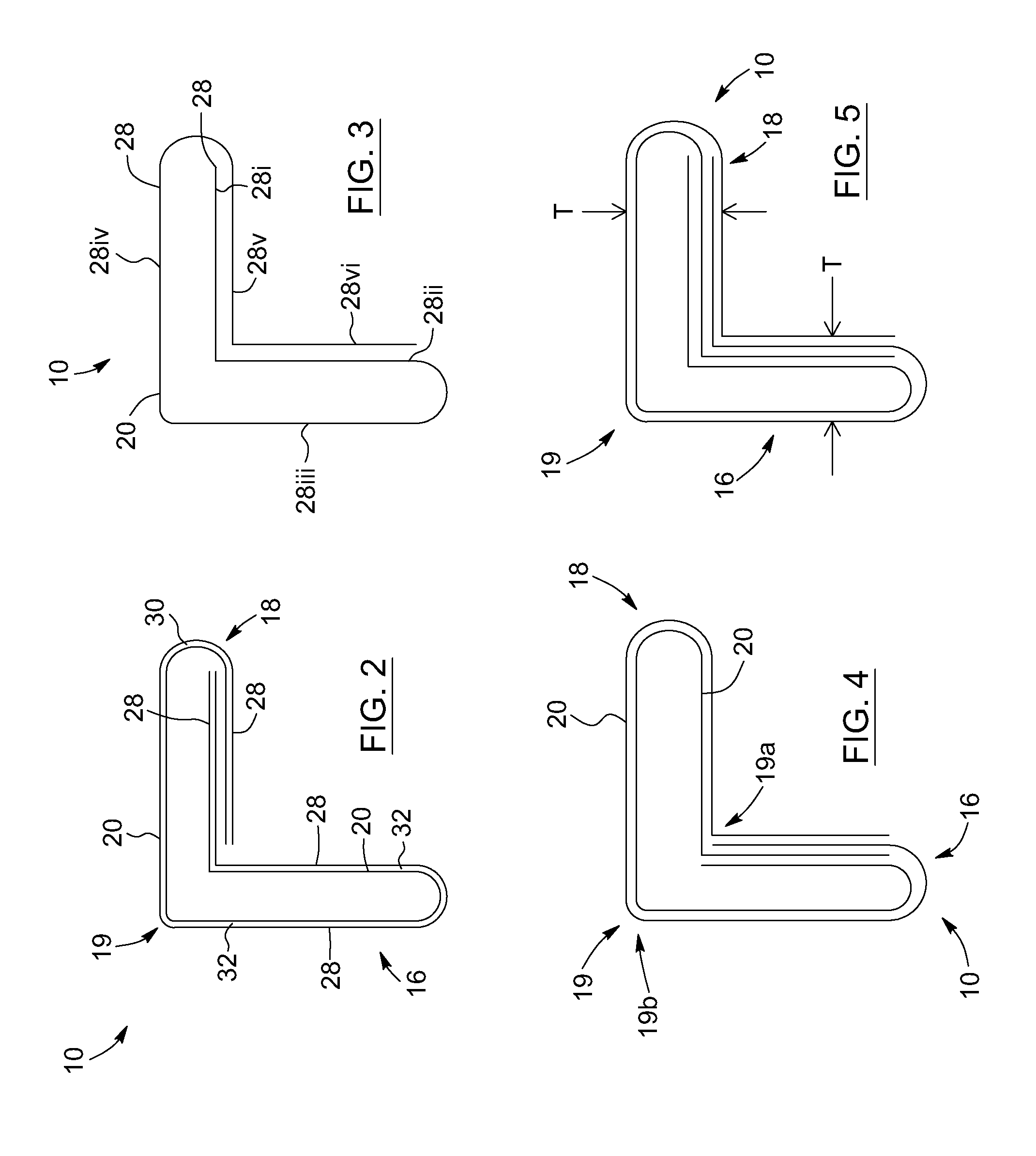
[0056]In the following description, the same numerical references refer to similar elements. Furthermore, for the sake of simplicity and clarity, namely so as to not unduly burden the figures with several references numbers, not all figures contain references to all the components and features of the present invention and references to some components and features may be found in only one figure, and components and features of the present invention illustrated in other figures can be easily inferred therefrom. The embodiments, geometrical configurations, materials mentioned and / or dimensions shown in the figures are preferred, for exemplification purposes only.

[0057]Moreover, although the corner as herein described was primarily designed to be used to protect the corners and edges of merchandise during shipping and packaging, it may be used with other types of devices and / or products, and in other fields, as apparent to a person skilled in those arts.

[0058]Moreover, in the context o...


PUM


Abstract

The invention concerns an elongated protective corner for the transport and / or packaging of products. The corner has at least two non-corrugated paperboard plies combined together to create two perpendicular wings and an apex. The plies form multiple ply sections, and at least one of the ply sections of a given ply overlaps another ply section of the same ply. This overlapping arrangement gives the apex a resistance force of about 100 to about 500 lbs. The thickness of the corner can vary, with each wing being in the range of about 100 to about 250 points, and each ply is made from paperboard having a grammage of about 120 to about 380 g / m2. The resistance force can be determined by mounting the corner upon two blocks, and applying a force to the apex at a middle of the corner until a fracture is detected.

Description

FIELD OF THE INVENTION [0001]The present invention relates to protective devices to protect products from impacts, for example when stored or transported. More particularly, in its intended preferred use, the present invention relates to an improved paperboard corner to be mounted against merchandise so as to protect the merchandise during packaging and moving.BACKGROUND OF THE INVENTION[0002]Known in the art are various paperboard forms or corners for protecting merchandise. The forms are usually mounted or fitted onto the corners or edges of a product before the product is loaded into a packaging box, or shipped from one destination to another.[0003]In general, paperboard forms are constructed from multiple plies of a paper product such as corrugated cardboard or other paper products known in the art. A “ply” of paperboard can be a single paperboard sheet, or can be composed of many paperboard layers laminated or adhered together so as to form the ply. In order to make the known p...

Claims


Application Information

Patent Timeline
Patent Type & Authority Applications(United States)
IPC IPC(8): B65D81/05B31D3/04B31B11/00
CPCB65D81/054B31D3/04B31B11/00B31D5/006B65D71/04B31B2120/25B31C99/00B31B50/73B31B50/624
Inventor D'ANGLADE, PIERRE-MICHEL
Owner ABZAC CANADA INC
Why Eureka
Try Eureka