
Particle beam device and method for operating a particle beam device

a particle beam and beam technology, applied in the direction of material analysis using wave/particle radiation, instruments, nuclear engineering, etc., to achieve the effect of good detection signal, good image of object, and good detection signal

Active Publication Date: 2014-03-13
CARL ZEISS MICROSCOPY GMBH
View PDF3 Cites 7 Cited by
  • Summary
  • Abstract
  • Description
  • Claims
  • Application Information

AI Technical Summary

Benefits of technology

The patent describes a system and device that uses a magnetic unit to improve the detection and examination of objects. The system can generate multiple crossovers, which helps to improve the image of the object by using higher energy particles. The device can also examine objects at a small working distance without the problem of a detection hole. Additionally, the device has the ability to switch between different modes to achieve both good detection and high resolution images. The accelerating voltage in the device is also independent of the beam generator used, which allows for greater voltage levels.

Problems solved by technology

The above-described problem of the detection hole is no longer present in the system described herein or present to only a minor degree such that still sufficient image information is available, such that a good image of the object is achievable.

Method used


Image

  • Particle beam device and method for operating a particle beam device
  • Particle beam device and method for operating a particle beam device
  • Particle beam device and method for operating a particle beam device

Examples


Embodiment Construction

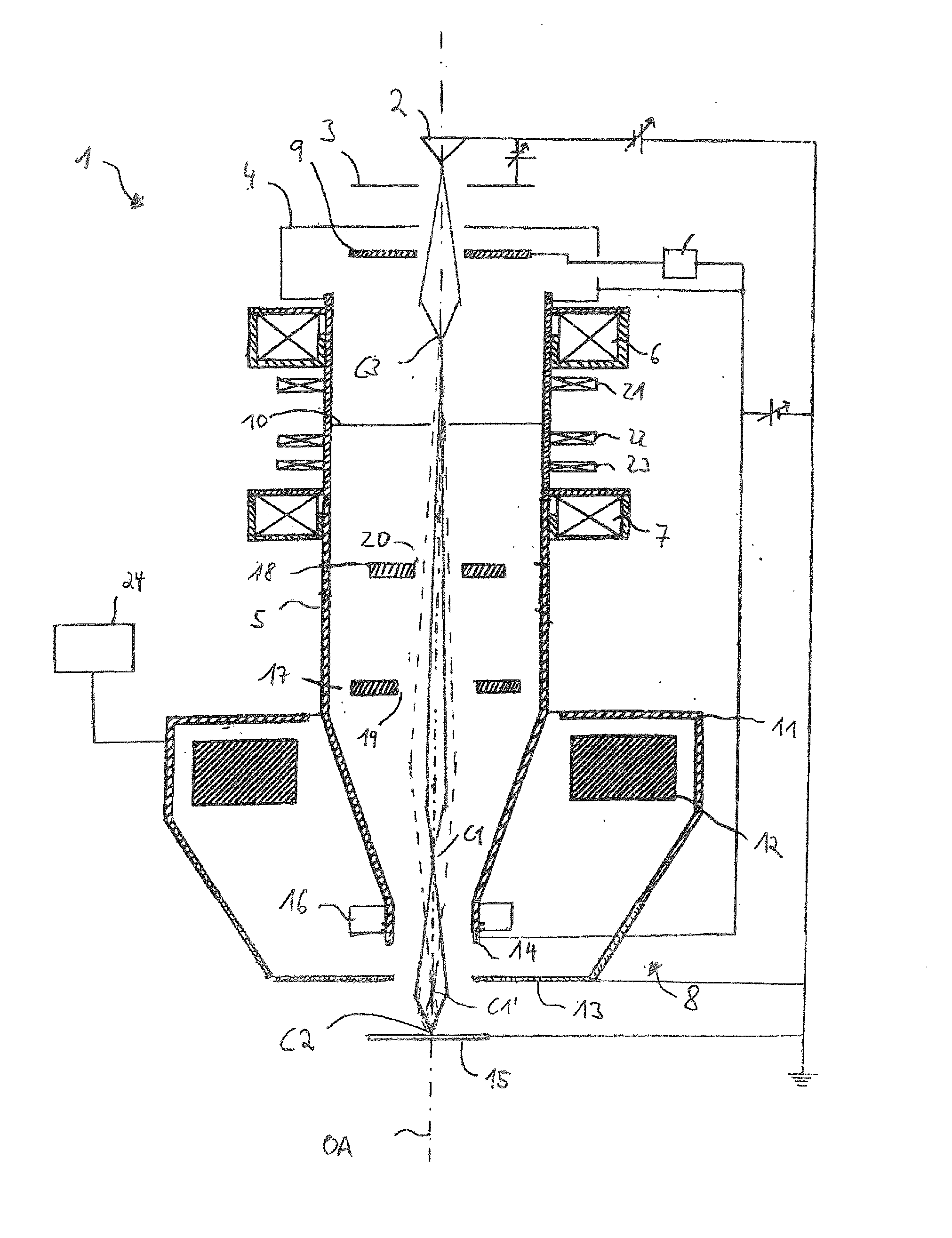
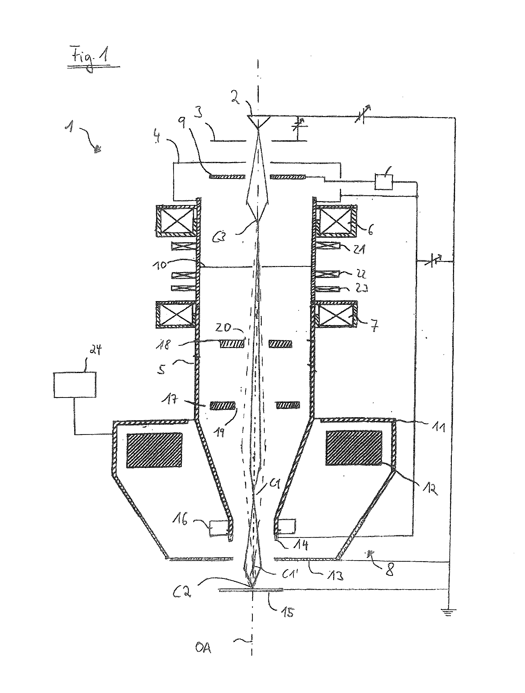
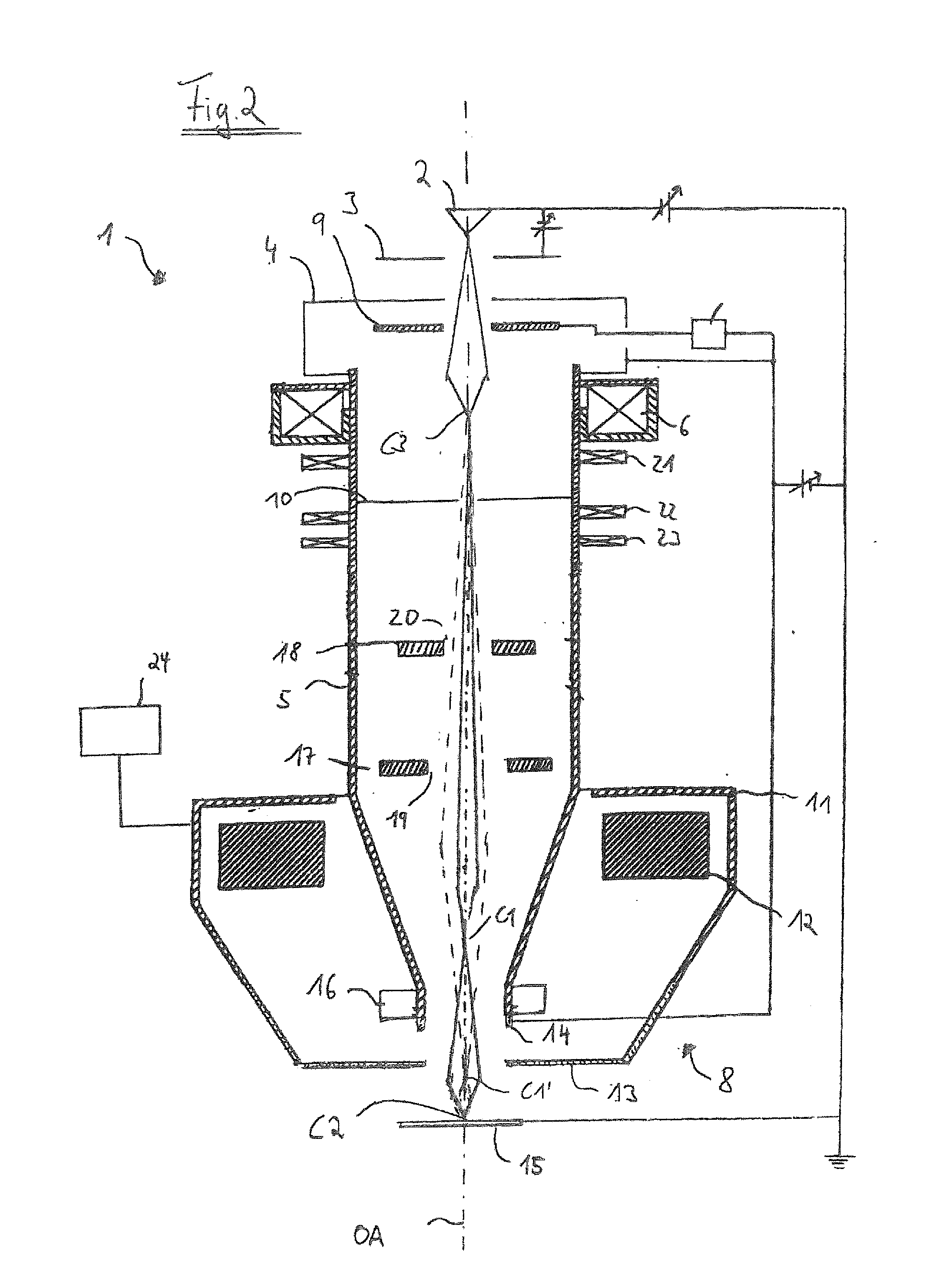
[0036]The system described herein will be explained in more detail using a particle beam device in the form of a scanning electron microscope (SEM). However, it is expressly noted that the system described herein is not limited to an SEM. Rather, the system described herein can be realized in any particle beam device, in particular in an ion beam device or in particular in a field ion microscope.

[0037]FIG. 1 shows a schematic illustration of a first exemplary embodiment of an SEM 1. The SEM 1 has a beam generator in the form of an electron source 2 (cathode), an extraction electrode 3 and an anode 4, which is placed onto one end of a beam guiding tube 5 of the SEM 1. The electron source 2 is constructed for example as a thermal field emitter. However, the system described herein is not limited to such an electron source. Rather, any electron source can be used.

[0038]Electrons emerging from the electron source 2 form a primary electron beam. The electrons are accelerated to anode pot...


PUM

PropertyMeasurementUnit
energyaaaaaaaaaa
energyaaaaaaaaaa
energyaaaaaaaaaa

Abstract

A particle beam device, in particular an electron beam device, is provided having a beam generator for generating a primary particle beam, an objective lens for focusing the primary particle beam onto an object, and a detector for detecting particles emitted by the object. The objective lens has at least one magnetic unit, with the magnetic unit generating at least one first crossover and at least one second crossover. The first crossover is arranged in the objective lens or in a region between the objective lens and the object. The second crossover is arranged at the object. The device permits the examination of the object using particles which have a low energy, with good imaging properties. A method for operating the particle beam device is also provided.

Description

TECHNICAL FIELD[0001]This application relates to a particle beam device, in particular an electron beam device, having a beam generator for generating a primary particle beam, having an objective lens for focusing the primary particle beam onto an object plane (or onto an object) and having a detector for detecting particles emitted by the object plane (or by the object). This application furthermore relates to a method for operating the particle beam device.BACKGROUND OF THE INVENTION[0002]Electron beam devices, in particular scanning electron microscopes are used, for example to examine surfaces of objects (specimens). In a scanning electron microscope, a primary electron beam having electrons is to this end generated using the beam generator. The primary electron beam is focused onto the object to be examined by an objective lens. It is also known to guide the primary electron beam in a raster-scan pattern over the surface of the object to be examined using a deflection device. I...

Claims


Application Information

Patent Timeline
Patent Type & Authority Applications(United States)
IPC IPC(8): G01N23/225
CPCG01N23/225H01J2237/2538H01J37/10H01J37/265H01J37/28H01J2237/0475H01J2237/24475H01J2237/2449
Inventor ALBIEZ, MICHAEL
Owner CARL ZEISS MICROSCOPY GMBH
Learn More