
Stator for rotary electric machine and method for manufacturing the stator

Active Publication Date: 2014-03-13
MITSUBISHI ELECTRIC CORP
View PDF6 Cites 15 Cited by
  • Summary
  • Abstract
  • Description
  • Claims
  • Application Information

AI Technical Summary

Benefits of technology

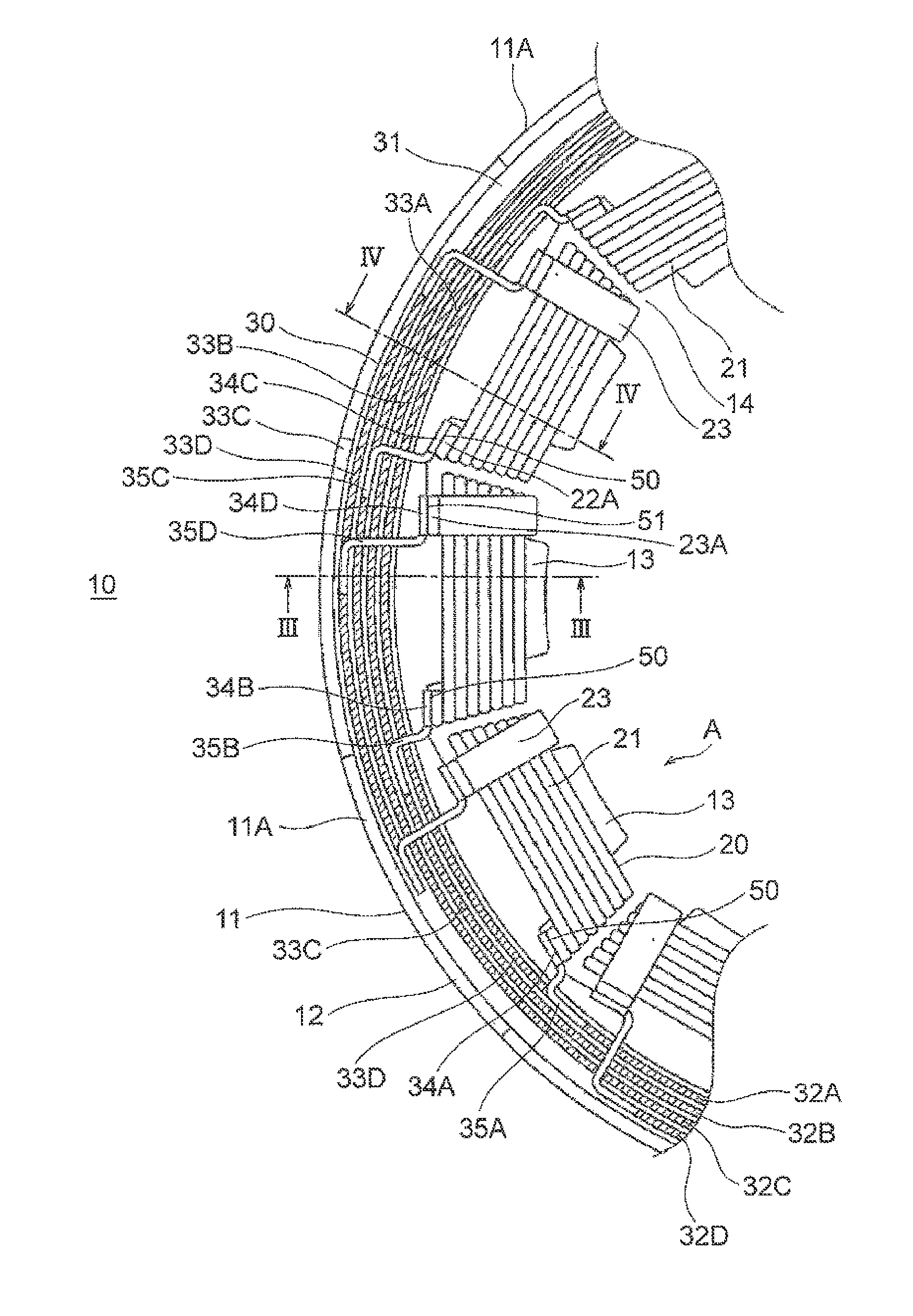
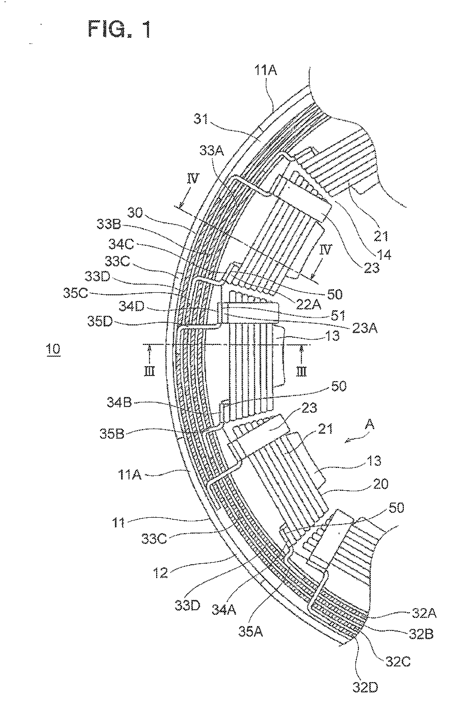
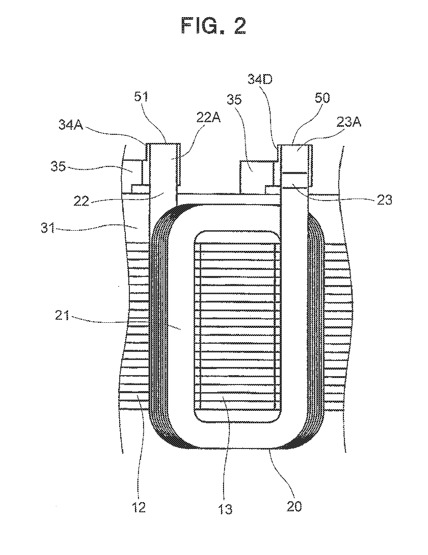
The present invention provides a stator for a rotary electric machine that ensures a safe distance between the innermost diameter portion of the coil and the coil-main body portion, reducing the space needed on the stator core and allowing for a smaller size in the axial direction.

Problems solved by technology

Therefore, there is a problem in that a space for the bulge is required to be ensured on the end surface of the stator core.
Therefore, there is a problem in that the space for providing the connecting wire is required to be increased on the end surface of the stator core.

Method used


Image

  • Stator for rotary electric machine and method for manufacturing the stator
  • Stator for rotary electric machine and method for manufacturing the stator
  • Stator for rotary electric machine and method for manufacturing the stator

Examples


second embodiment

[0088]FIG. 11 is a sectional side view illustrating a principal part of the stator 10 according to a second embodiment of the present invention, and FIG. 12 is a diagram illustrating the relationship between the potential difference and the electric field intensity between the second connecting wire 23 and the coil end CE of the coil main-body portion 21 illustrated in FIG. 11 and the position in the radial direction of the stator 10 (position in the R-direction).

[0089]In this embodiment, each of the second connecting wires 23 includes a third bent portion 27 formed between the first bent portion 24 and the second bent portion 25.

[0090]The first bent portion 24 is bent so that a portion of the second connecting wire 23 between the first bent portion 24 and the third bent portion 27 has approximately the same height based on the end surface of the stator core 11 as a reference.

[0091]The third bent portion 27 is configured so that the clearance T between the third bent portion 27 and ...

third embodiment

[0106]FIG. 14 is a sectional view illustrating a principal part of the stator 10 according to a third embodiment of the present invention.

[0107]In the third embodiment, the first connecting wire 22 drawn from the outer diameter side of the stator core 11 projects from the outer-diameter side end portion of the coil main-body portion 21 outward in the axial direction of the stator core 11. The first connecting wire 22 is then bent to the outer diameter side of the stator core 11 at a first bent portion 28, then extends outward in the radial direction of the stator core 11, and is bent again outward in the axial direction of the stator core 11 at a second bent portion 29.

[0108]The remaining configuration is the same as that of the stator 10 according to the first embodiment.

[0109]In the third embodiment, the first connecting wire 22 is also provided with the first bent portion 28 and the second bent portion 29 so that the first connecting wire 22 is formed to have a crank-like shape. ...


PUM

PropertyMeasurementUnit
Angleaaaaaaaaaa
Currentaaaaaaaaaa
Lengthaaaaaaaaaa

Abstract

Provided is a stator for a rotary electric machine, capable of reducing a space on an end surface of a stator core on an inner diameter side to reduce a size in an axial direction to realize a compact size by maintaining an insulating distance corresponding to a potential difference. In the stator for a rotary electric machine according to the present invention, a coil portion includes a coil main-body portion (21) and a second connecting wire (23). The second connecting wire (23) includes a first bent portion (24) and a second connecting-wire end portion (23A). The second connecting wire (23) is configured so that a differential value of a length z in the axial direction of the stator to a length r in the radial direction of the stator is Δz / Δr≧0.

Description

BACKGROUND OF THE INVENTION[0001]1. Field of the Invention[0002]The present invention relates to a stator for a rotary electric machine, including a stator core and a stator winding provided to the stator core, which is configured by electrically connecting a plurality of coil portions formed by winding conductors around teeth to terminal members through connecting wires of the coil portions, and a method for manufacturing the stator.[0003]2. Description of the Related Art[0004]A rotary electric machine used as a driving source of electric automobiles and hybrid automobiles generally includes a ring-shaped stator core which has a plurality of teeth, each projecting in an inner-diameter direction, provided at constant intervals in a circumferential direction. A coil portion formed by winding a conductor is mounted to each of the teeth of the stator core (for example, see Japanese Patent No. 4340740).[0005]For the stator as described above, the coil portions are formed into a unit in ...

Claims


Application Information

Patent Timeline
IPC IPC(8): H02K3/50H02K15/00H02K3/28
CPCH02K3/50H02K15/0056H02K3/28H02K3/325H02K3/522H02K15/0062H02K2203/09Y10T29/49009Y10T29/49071Y10T29/49073H02K15/022H02K3/04H02K3/32H02K15/12H02K15/0407H02K15/02
Inventor ISODA, HITOSHINAKAMURA, MASASHINISHIMURA, SHINJI
Owner MITSUBISHI ELECTRIC CORP
Learn More