
Electric motor torque control

a technology of torque control and electric motor, which is applied in the direction of hybrid vehicles, dynamo-electric converter control, dynamo-electric gear control, etc., can solve the problems of not always being able to operate at this condition, and being associated with higher losses for combinations

Active Publication Date: 2014-03-13
FORD GLOBAL TECH LLC
View PDF12 Cites 9 Cited by
  • Summary
  • Abstract
  • Description
  • Claims
  • Application Information

AI Technical Summary

Benefits of technology

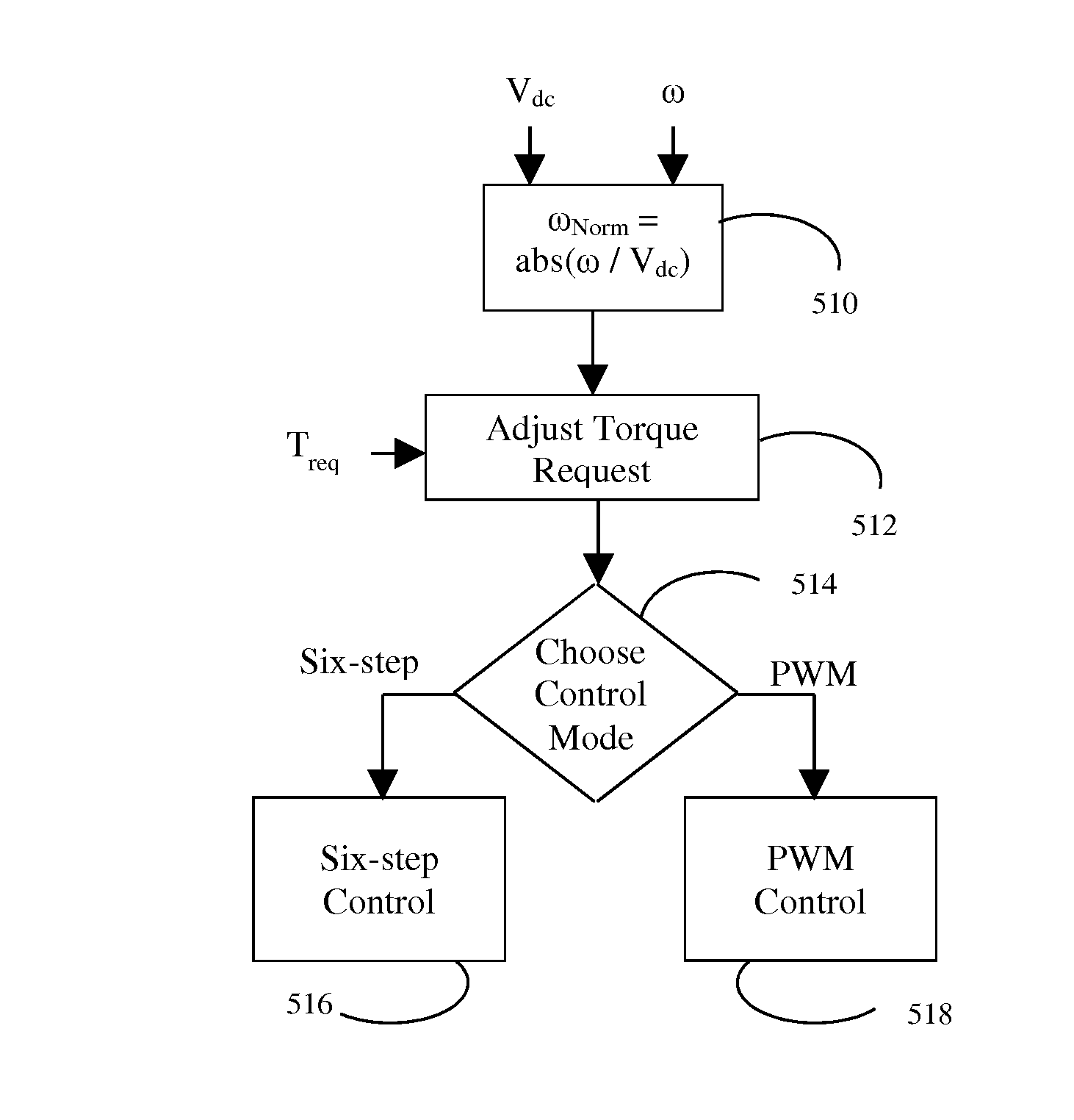
This patent describes a method for controlling the torque output of an electric machine using an inverter. The method involves calculating the speed of the machine's rotor and using this information to determine the desired torque output. The inverter then controls the current in the machine's winding to achieve the desired torque. The patent also includes a vehicle control system that uses this method to regulate the torque output of a synchronous motor. The system includes an inverter that is connected to the motor and an electrical bus. The controller commands the inverter to cycle among different states to achieve the desired torque output. This method ensures efficient and accurate control of the electric machine's torque output.

Problems solved by technology

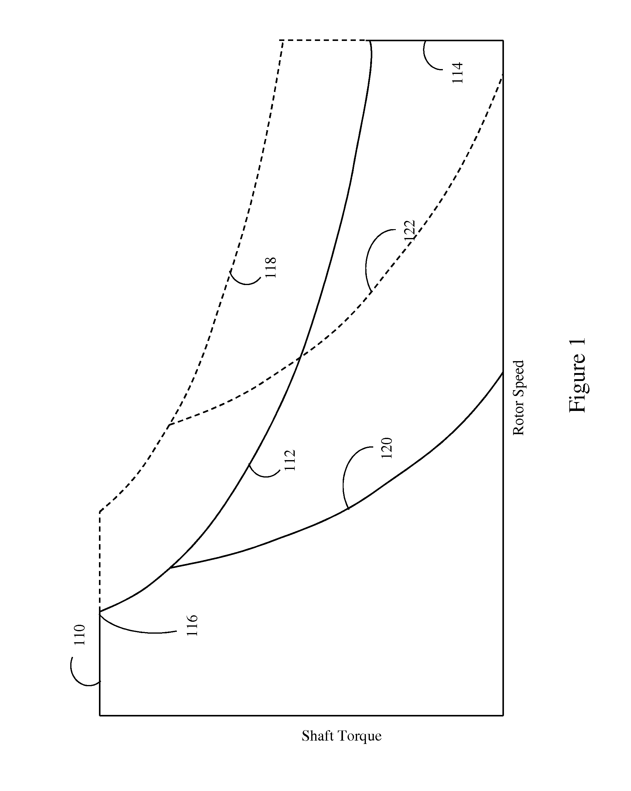
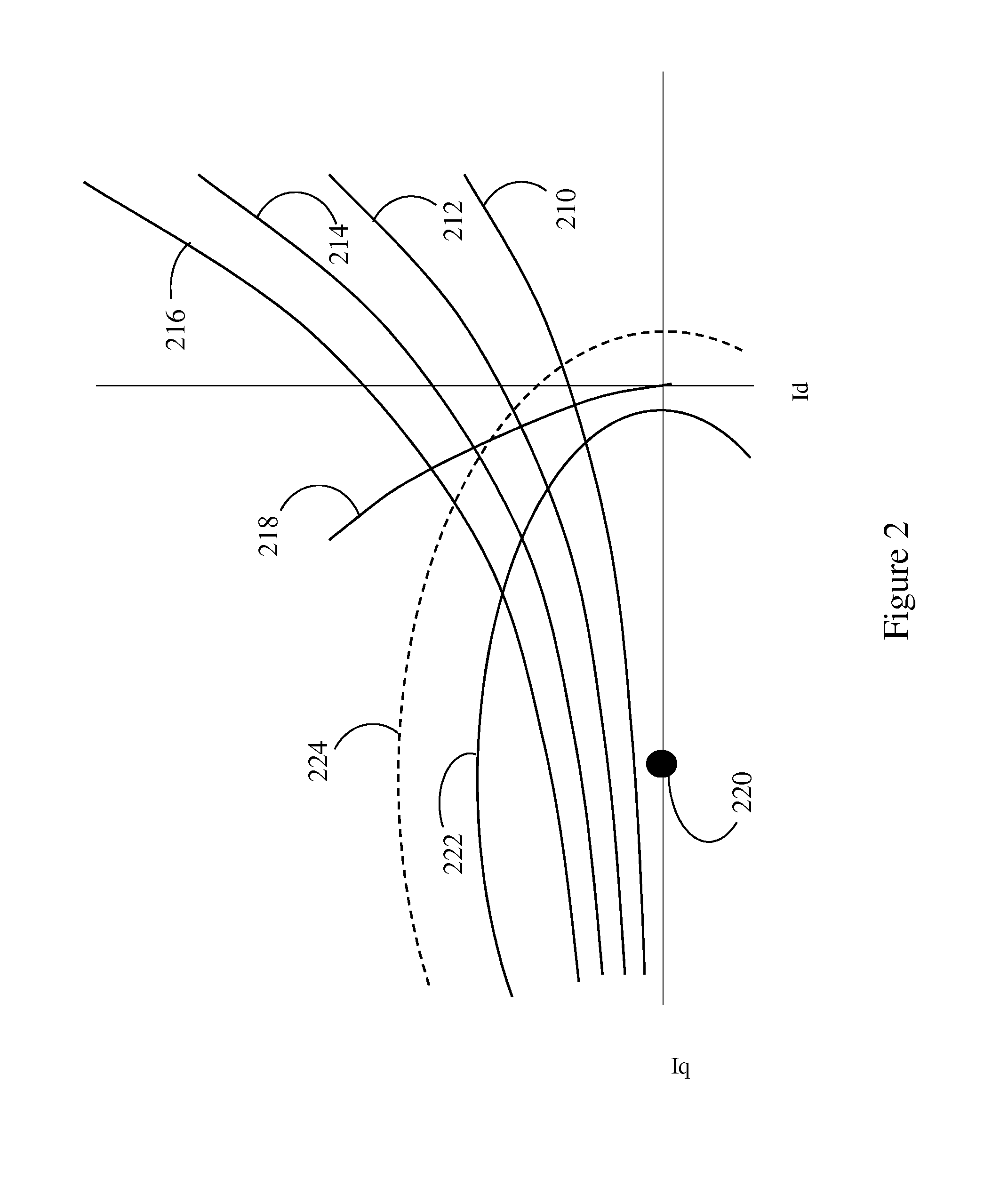
Although every point along each of these curves produces the same output torque, some combinations will be associated with higher losses than others.
However, it is not always possible to operate at this condition.

Method used


Image

  • Electric motor torque control
  • Electric motor torque control
  • Electric motor torque control

Examples


Embodiment Construction

[0019]Embodiments of the present disclosure are described herein. It is to be understood, however, that the disclosed embodiments are merely examples and other embodiments can take various and alternative forms. The figures are not necessarily to scale; some features could be exaggerated or minimized to show details of particular components. Therefore, specific structural and functional details disclosed herein are not to be interpreted as limiting, but merely as a representative basis for teaching one skilled in the art to variously employ the present invention. As those of ordinary skill in the art will understand, various features illustrated and described with reference to any one of the figures can be combined with features illustrated in one or more other figures to produce embodiments that are not explicitly illustrated or described. The combinations of features illustrated provide representative embodiments for typical applications. Various combinations and modifications of ...


PUM


Abstract

A vehicle includes one or more inverter-fed electric machines such as permanent magnet synchronous motors. In response to a torque request, a controller issues commands to an inverter calculated to cause the motor to produce the requested torque. A method of operating the inverter may determine the commands based on the ratio of rotor speed to inverter input voltage, reducing the approximation error associated with multi-dimensional lookup tables. When the speed and voltage vary while maintaining a constant ratio and constant torque request, the issued commands produce a winding current in the electrical machine with constant direct and quadrature components.

Description

TECHNICAL FIELD[0001]This disclosure relates to control of electric motors.BACKGROUND[0002]Permanent magnet synchronous motors (PMSMs) are utilized in various applications because they have generally favorable efficiency characteristics relative to other types of motors. Typically, PMSMs have three separate electrical windings within the stator which are each powered by alternating current (AC) voltages Va, Vb, and Vc. In operation, the winding currents Ia, Ib, and Ic each oscillate at a frequency proportional to the rotor speed and are separated by 120 degrees in phase from one another. These winding currents induce a rotating magnetic field which may be out of phase with the rotor. The resulting shaft torque depends upon both the magnitude of the magnetic field and the phase angle relative to the rotor.[0003]For convenience, the winding voltages and currents may be represented by vectors with respect to a rotating reference frame that rotates with the rotor. The mapping between ro...

Claims


Application Information

Patent Timeline
IPC IPC(8): H02P21/14B60L50/15B60L50/16
CPCH02P21/148H02P23/009B60L15/02B60L15/025B60L2210/30B60L2210/40B60L2220/14B60L2240/12B60L2240/421B60L2240/423B60L2240/429B60L2240/441B60L2240/529B60L2250/26B60L2260/42B60L2240/527H02P23/30B60L50/61B60L50/16H02P21/20Y02T10/64Y02T10/62Y02T10/72Y02T10/7072Y02T10/70
Inventor LUEDTKE, DANIELDEGNER, MICHAEL W.
Owner FORD GLOBAL TECH LLC
Learn More