Multiple membranes for removing voc's from liquids

Inactive Publication Date: 2014-03-13
ROHM & HAAS CO +1
4 Cites 4 Cited by

AI-Extracted Technical Summary

Problems solved by technology

Latex paints often contain VOCs at levels that produce undesirable odors.
Although these conventional stripping processes are widely used for treating aqueous streams, these techniques are not as efficient for removing VOCs from latexe...

Method used

[0028]The present invention relates to a process for removing VOCs from a liquid stream by way of multiple membranes, each of which are advantageously housed in modules, which membranes provide an efficient means of stripping VOCs from a liquid feed such as latex, surfactant-laden wastewater, or brine, with internal recycle of a stripping gas. The process of the present invention strips VOCs from the feed with minimal consumption of stripping gas, such as air or nitrogen or steam, for good economy of operation. The process minimizes stripping gas by using multi-stage countercurrent processing with multiple membrane modules and by recycling (recirculating) a portion of the stripping gas within the process. In one embodiment of the invention, stripping gas is recycled to boost the gas velocity within a given module to improve mass transfer efficiency, thereby further reducing the amount of stripping gas required to strip VOCs to a desired level. In another embodiment, the liquid feed is recycled to boost the liquid velocity within a module in order to improve mass transfer efficiency, thereby reducing the transfer area and module size to strip VOCs to a desired level.
[0031]One or more of the membranes may also comprise a composite membrane, which is a thin nanoporous or nonporous film supported on the surface of a thicker support membrane that provides mechanical strength. This support membrane is preferably macroporous, with pore diameters typically in the range of 1000 nm to 10,000 nm, to facilitate transport to the discriminating film. The support membrane may be made of any polymer with the required mechanical strength, including hydrophobic and hydrophilic polymers.
[0034]VOCs pass from the liquid through the first membrane (22) and are carried away from the first module (20) by a flowing stream of stripping gas, which is countercurrent to the liquid stream. The stripping gas is fed initially from an inlet (50) through the second membrane module (30) and then to the first membrane module (20) across a second surface (22b) of the first membrane (22). A part of the vapor stream containing the VOCs leaves the first module (20) and flows to the vapor outlet (60). A part of the vapor stream containing the VOCs may also be recirculated back to the inlet of the first module (20). The stripping gas, which is passed across the second surface (32b) of the second membrane (32), is preferably not reci...

Benefits of technology

[0015]The present invention addresses a need in the art by providi...

Abstract

The present invention relates to a process for removing volatile organic compounds (VOCs) from a liquid stream using multiple membranes that are permeable to the VOCs but impermeable to the liquid.

Application Domain

MembranesWater contaminants +4

Technology Topic

Volatile organic compoundEnvironmental chemistry

Image

  • Multiple membranes for removing voc's from liquids
  • Multiple membranes for removing voc's from liquids
  • Multiple membranes for removing voc's from liquids

Examples

  • Experimental program(2)

Example

EXAMPLE
[0044]The following example is for illustrative purpose only and is not intended to limit the scope of the invention.

Example

Example 1
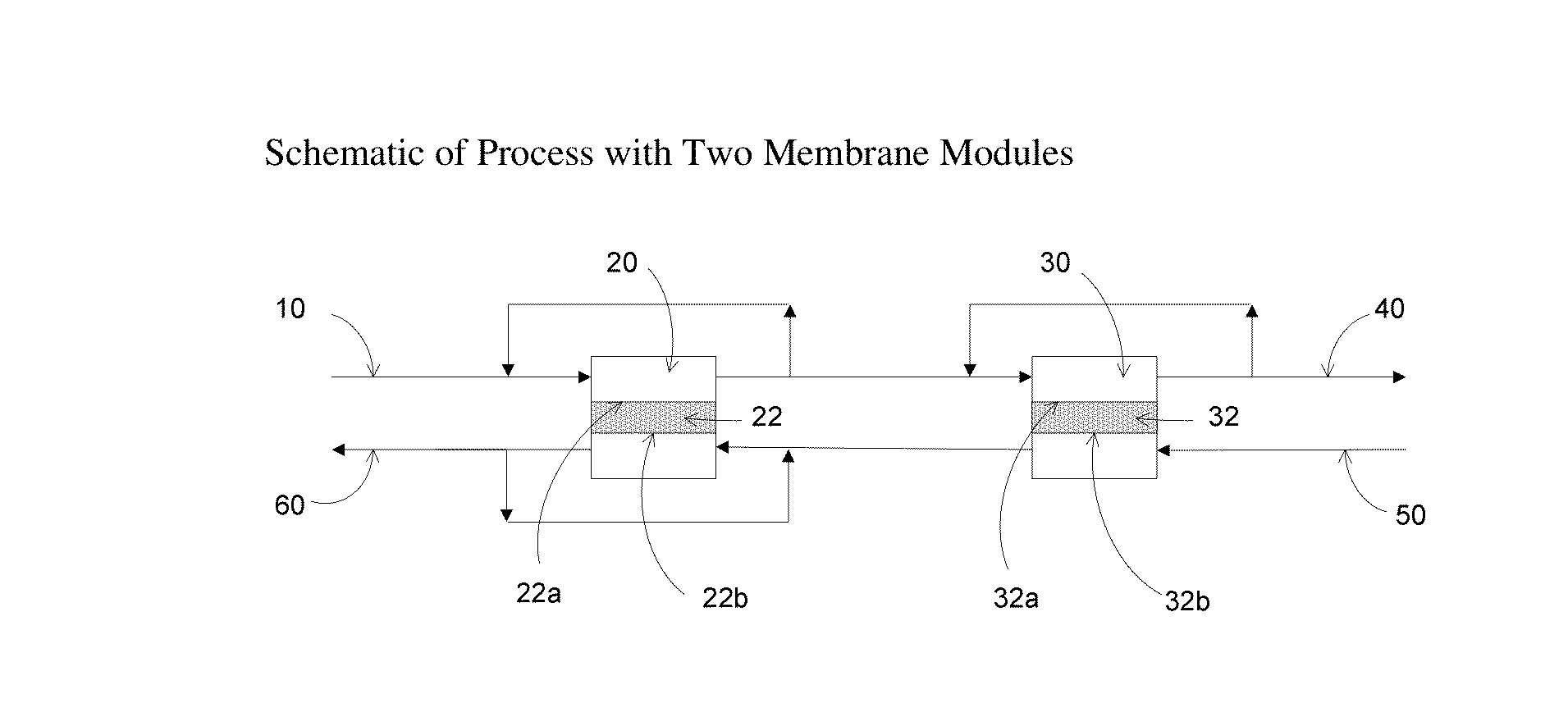
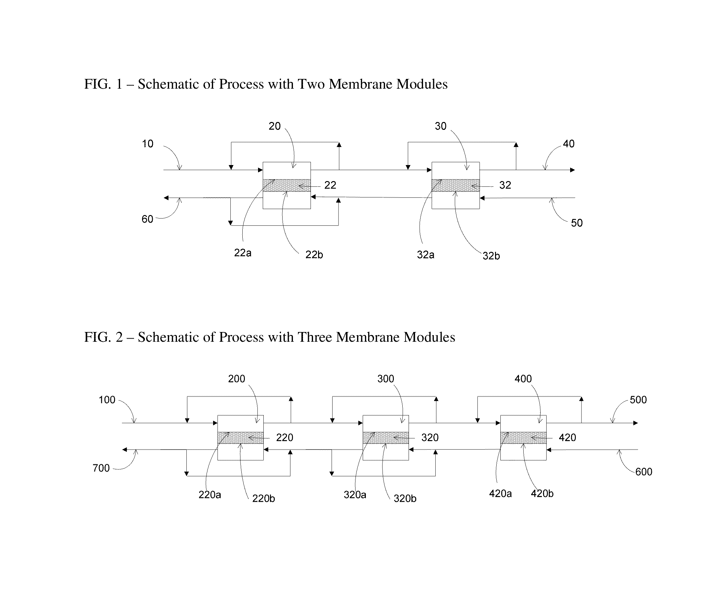
Extraction Optimization Using a 2-Stage Membrane
[0045]The following example demonstrates extraction optimization using a 2-stage membrane setup as shown in FIG. 1. The outlet latex VOC concentration for a 2-membrane system can be estimated when the inlet VOC concentration is known. If a latex inlet VOC concentration is 500 ppm and a feed rate of latex is 0.02 mL/s, the outlet VOC concentration is estimated to be 175 ppm using two membrane modules and no recycle of latex. The governing equation used for this calculation is as follows:
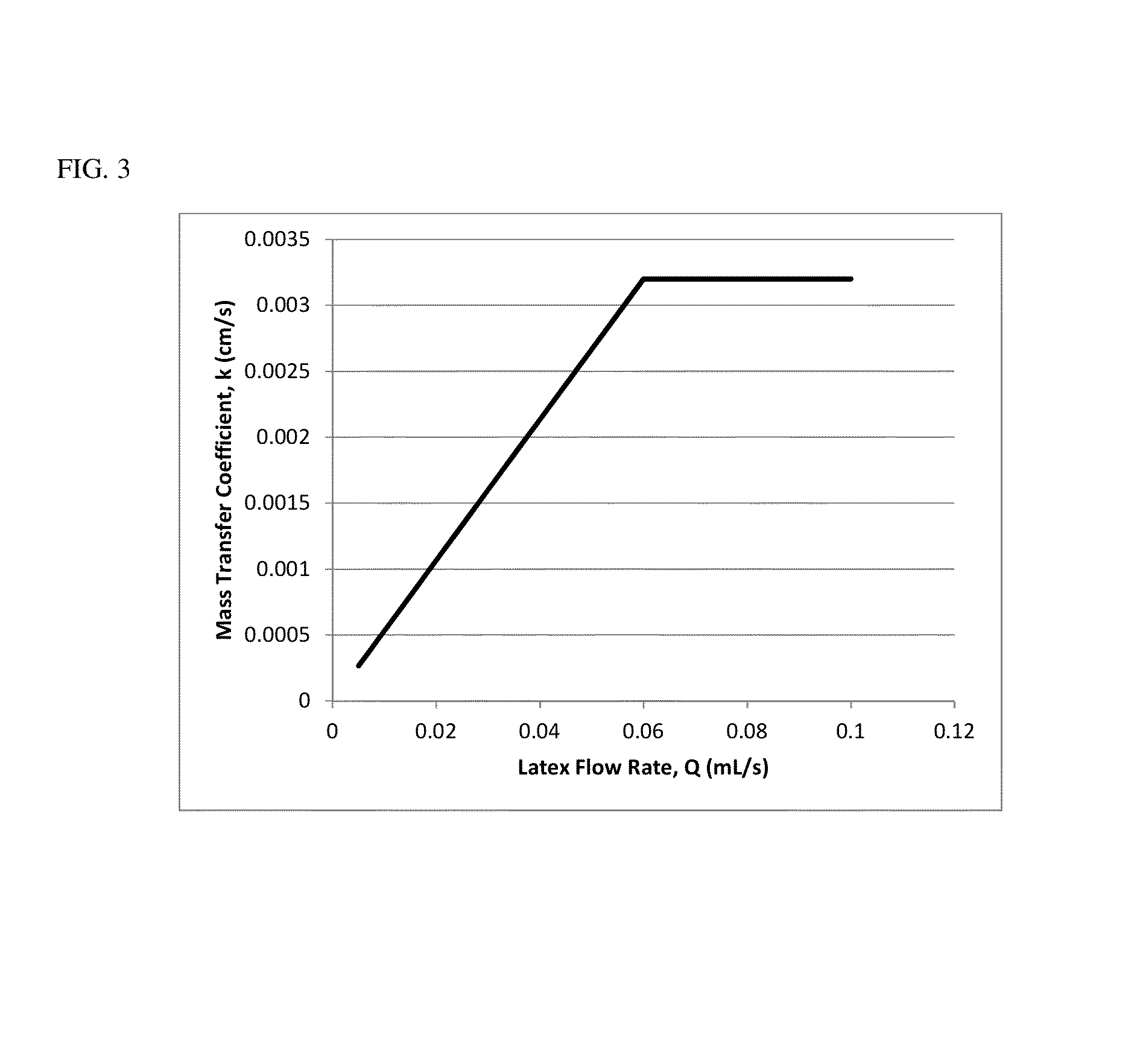
m ( C in - C out ) = k A ( C in - C out ) ln ( C in C out ) [0046] =flow rate of latex, mL/s [0047] in=concentration of VOC in feed latex, ppm [0048] out=concentration of VOC in exit latex, ppm [0049] =mass transfer coefficient, cm/s [0050] =membrane area, cm2
[0051]To lower the outlet VOC concentration, the recycle flow rate was increased but the net flow rate through each module was kept the same. For this example, enough latex was recycled to achieve a total flow rate to the module of 0.06 mL/s (0.04 mL/s recycle flow rate), which was the flow rate at which the mass transfer coefficient reached its peak. At this recycle rate, the exit VOC level was calculated to be 65 ppm.
[0052]No advantage to increasing the amount of recycle is realized once the mass transfer coefficient stops increasing. When the total flow through the module was increased to 0.08 mL/s, and 0.07 mL/s of the latex was recycled around the module, the exit VOC level was calculated to be 75 ppm, representing an increase of about 10 ppm. The optimum recycle rate is therefore 0.04 mL/s
[0053]FIG. 3 illustrates the relationship between the mass transfer coefficient across the membrane and the feed rate of the latex to the membrane. The latex is RHOPLEX™ AC261 Acrylic Latex (A Trademark of The Dow Chemical Company or Its Affiliates), and contains residual acetone, t-butanol, dibutyl ether, and butyl propionate. The mass transfer coefficient has the following dependence: a linear increase in mass transfer coefficient for flow rates up to about 0.06 mL/s and a flat region with no change in mass transfer coefficient for flow rates above 0.06 mL/s In these experiments the vapor feed is humidified air and its flow rate is not changed.

PUM

PropertyMeasurementUnit
Permeability

Description & Claims & Application Information

We can also present the details of the Description, Claims and Application information to help users get a comprehensive understanding of the technical details of the patent, such as background art, summary of invention, brief description of drawings, description of embodiments, and other original content. On the other hand, users can also determine the specific scope of protection of the technology through the list of claims; as well as understand the changes in the life cycle of the technology with the presentation of the patent timeline. Login to view more.

Similar technology patents

Filter structure capable of removing dust

PendingUS20210071904A1efficiently removeprevent deterioration of dust collection efficiency
Owner:CENDORI

Drilling tool, in particular for metallic materials

InactiveUS20090155008A1efficiently removelow static pressure
Owner:AUDI AG

Classification and recommendation of technical efficacy words

  • efficiently remove

Hollow fiber membrane module

InactiveUS20070163942A1efficiently removefacilitate preventing
Owner:TORAY IND INC

Anhydrous processing of methane into methane-sulfonic acid, methanol, and other compounds

InactiveUS20080161591A1increase solubility and reaction rateefficiently remove
Owner:RICHARDS ALAN K

Tobacco free hookah smoking system

InactiveUS20140069446A1efficiently removedecrease in size
Owner:BEDROCK HLDG TRUST 2012
Why Eureka
Try Eureka