Jump liner for push-pull mig torch

Active Publication Date: 2014-03-20
ILLINOIS TOOL WORKS INC
View PDF5 Cites 1 Cited by
  • Summary
  • Abstract
  • Description
  • Claims
  • Application Information

AI Technical Summary

Benefits of technology

[0008]A push-pull MIG welding torch in accordance with the present invention includes a handle and a gooseneck having front and back ends. The handle is connected to the back end of the gooseneck. A contact tip assembly is connected to the front end of the gooseneck. A jump liner extends through the gooseneck from the handle to the contact tip assembly. The jump liner includes an elongated tubular body having front and back ends. The tubular body is made of a flexible plastic material. A front adapter is disposed at the front en

Problems solved by technology

Current push-pull MIG torch designs provide adequate sealing between the jump liner and the gooseneck or body block inside the handle, but do not provide sealing between the jump liner and the retaining head or contact tip at the front end.
Therefore, significant gaps are required between a plastic jump liner and the metal parts of the welding torch to allow for expansion and contract

Method used


Image

  • Jump liner for push-pull mig torch
  • Jump liner for push-pull mig torch
  • Jump liner for push-pull mig torch

Examples


Example

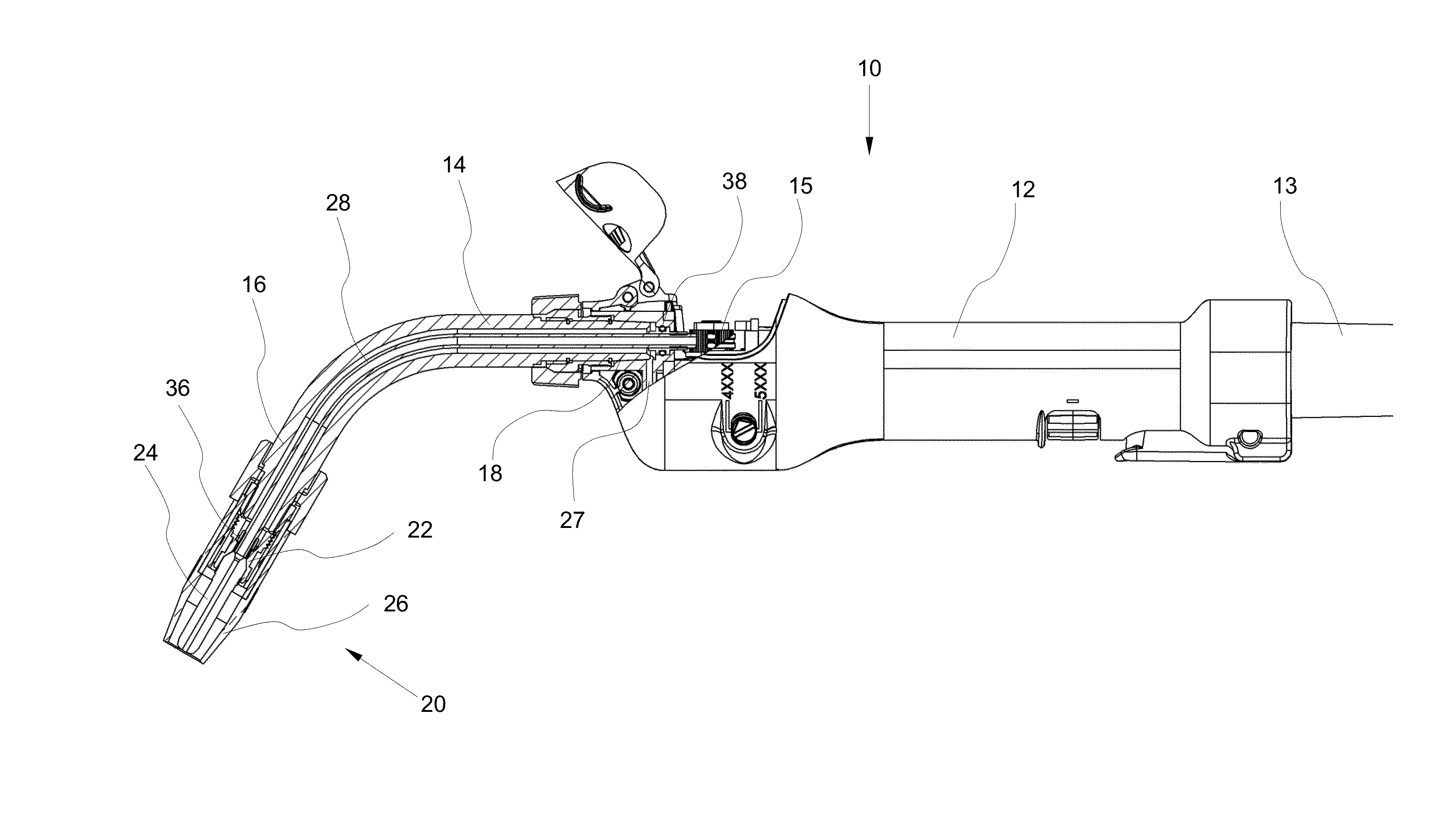
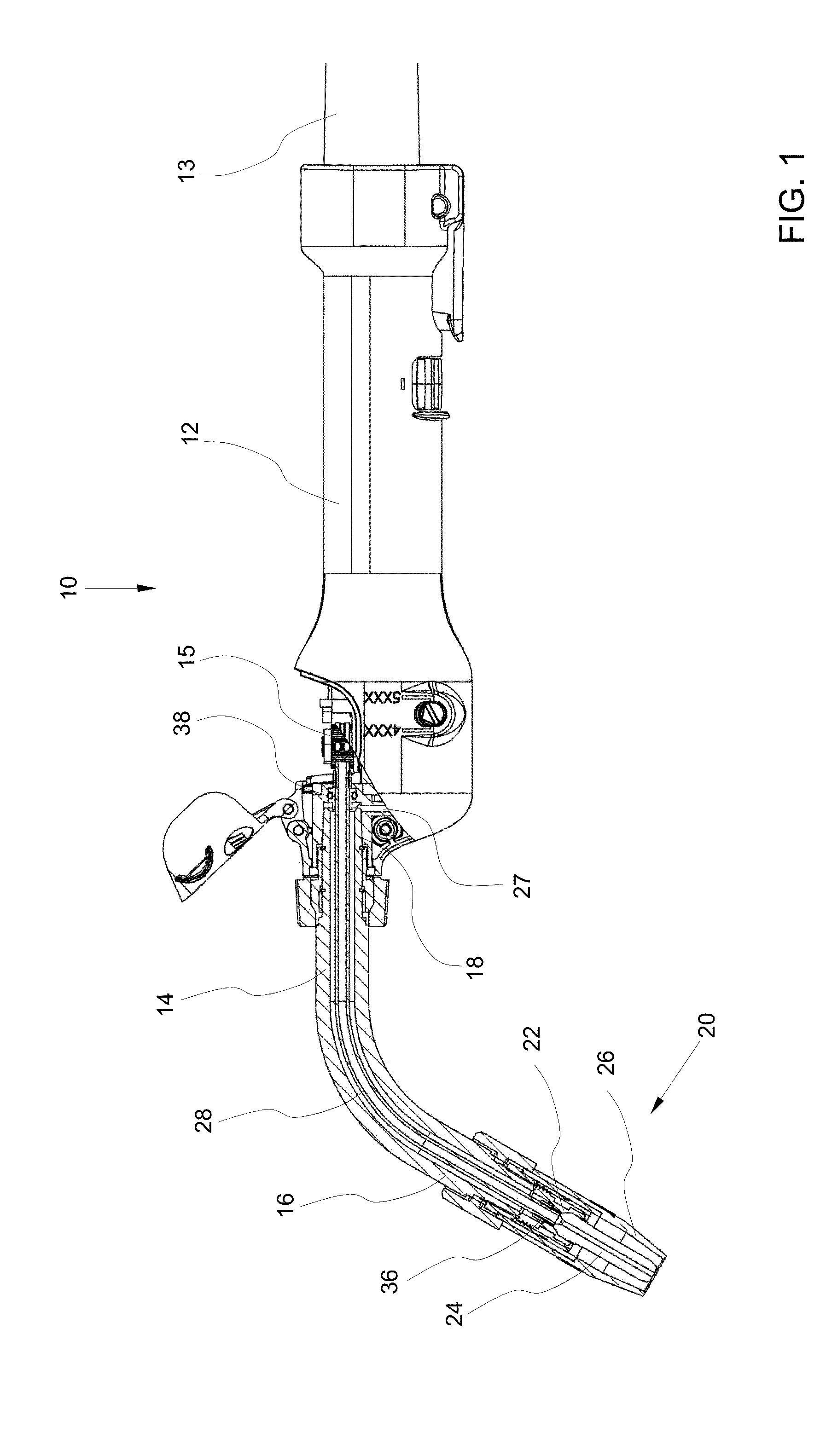
[0016]Referring now to the drawings in detail, numeral 10 generally indicates a push-pull MIG welding torch. The push-pull MIG welding torch 10 includes a jump liner in accordance with the present invention. The jump liner according to the present invention provides proper sealing for preventing leakage of shielding gas, while also tolerating the properties of plastic materials which typically form the jump liner. The jump liner also protects the plastic tubular body of the jump liner so that it will not close at the front end (contact tip end) at elevated temperatures. The jump liner is also more tolerant of variations in the length of the plastic tubular body.

[0017]As shown in FIG. 1, the push-pull MIG welding torch 10 generally includes a handle 12 and a gooseneck 14 having a front end 16 and a back end 18. The handle 12 is connected to the torch cable assembly 13 at one end and to the back end 18 of the gooseneck at the other end. A contact tip assembly 20 is connected to the fr...


PUM

PropertyMeasurementUnit
Temperatureaaaaaaaaaa
Diameteraaaaaaaaaa
Electrical resistanceaaaaaaaaaa

Abstract

A jump liner for a push-pull MIG welding torch includes an elongated tubular body having front and back ends. The tubular body is made of a flexible plastic material. A front adapter is disposed at the front end of the tubular body. The front adapter is fittable in a retaining head of the torch. A back adapter is disposed at the back end of the tubular body. The back adapter is fittable in a gooseneck or body block of the welding torch. The front adapter provides sealing between the jump liner and the retaining head to prevent back flow leakage of shielding gas, and the front adapter prevents deformation of the tubular body at elevated temperatures. The back adapter provides sealing between the jump liner and the gooseneck or body block.

Description

TECHNICAL FIELD[0001]This invention relates to push-pull MIG welding torches, and more particularly to a jump liner for a push-pull welding torch.BACKGROUND OF THE INVENTION[0002]A push-pull MIG welding system generally includes a wire feeder, and a welding torch connected to the wire feeder. Electrode welding wire (typically aluminum), shielding gas, welding current, and / or coolant are transferred inside the welding torch. The welding torch includes a handle connected at a rear end to a cable assembly and at a front end to a gooseneck which terminates in a contact tip assembly. The wire feeder includes a pushing drive roll mechanism that pushes the welding wire through the cable assembly to the handle. A pulling drive roll mechanism in the torch handle pulls the welding wire from the cable assembly and sends it forward through the gooseneck to the contact tip assembly. A tubular jump liner typically extends from the torch handle to the contact tip assembly to protect the welding wi...

Claims


Application Information

Patent Timeline
IPC IPC(8): B23K9/10
CPCB23K9/26B23K9/295
Inventor COSSETTE, ROMEO N.MA, TIEJUNBONDY, CRAIG M.ARCAND, JEFFERY K.GARVEY, PAUL W.ROEHL, CHRIS
Owner ILLINOIS TOOL WORKS INC
Why Eureka
Try Eureka