Compact waveguide termination

Inactive Publication Date: 2014-03-20
ELECTRONICS & TELECOMM RES INST
View PDF4 Cites 1 Cited by
  • Summary
  • Abstract
  • Description
  • Claims
  • Application Information

AI Technical Summary

Benefits of technology

[0009]In a compact waveguide termination according to the exemplary embodiments of the present invention, a substrate formed with the thin film resistor, of which the patterns are configured easily and is disposed at the central portion of the waveguide at which the electric field is high is connected to the termination, thereby effectively attenuating or dissipating the input signal while maintaining t

Problems solved by technology

In particular, frequency characteristics may deteriorates due to manufacturing error at higher frequency band such as mill

Method used


Image

  • Compact waveguide termination
  • Compact waveguide termination
  • Compact waveguide termination

Examples


Embodiment Construction

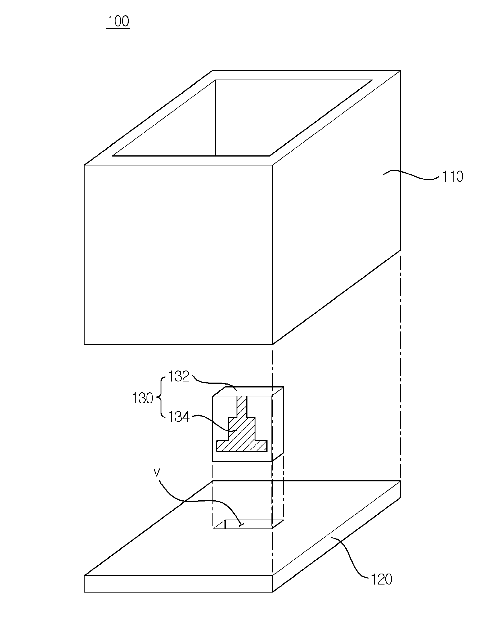
[0018]In describing components of exemplary embodiments, different reference numerals may be denoted for the components of the same name according to the drawings and the same reference numerals may be denoted for components in different drawings. However, even in this case, it does not mean that the corresponding components have different functions according to the exemplary embodiments or that the corresponding components have the same function in different exemplary embodiments and the functions of each component should be determined based on the description of each component in the corresponding exemplary embodiments.

[0019]In describing exemplary embodiments of the present invention, well-known functions or constructions will not be described in detail since they may unnecessarily obscure the understanding of the present invention.

[0020]In describing components of the exemplary embodiments, terms such as first, second, A, B, (a), (b), etc. may be used. These terms are used only ...


PUM


Abstract

Provided is a compact waveguide termination including: a waveguide, a termination coupled with the waveguide and formed with a groove, and a thin film resistor part coupled with the groove and configured to attenuate an input signal at a central region of the waveguide, thereby improving frequency performance.

Description

CROSS-REFERENCE TO RELATED APPLICATIONS[0001]This application claims priority to and the benefit of Korean Patent Application No. 10-2012-0103563 filed in the Korean Intellectual Property Office on Sep. 18, 2012, the entire contents of which are incorporated herein by reference.TECHNICAL FIELD[0002]The present invention relates to a compact waveguide termination, and more particularly, a compact waveguide termination with improved frequency performance.BACKGROUND ART[0003]Generally, in a wireless communication system using a millimeter wave band or higher band, a component of a waveguide type with a relatively larger volume than a microstrip line or a coaxial line has been continuously used due to excellent electrical performance.[0004]One of the waveguide component, such as a matched power combiner, and the like, as well as a component required for test is a waveguide termination.[0005]When the waveguide termination is simply used for tests, the volume of the waveguide termination ...

Claims


Application Information

Patent Timeline
IPC IPC(8): H01P1/26
CPCH01P1/264H01P1/26
Inventor UHM, MAN SEOKKWAK, CHANG SOOYUN, SO HYEUNCHOI, JANG SUP M.LEE, HONG YEOLSHIN, DONG HWANNOH, YOUN SUBYOM, IN BOK
Owner ELECTRONICS & TELECOMM RES INST
Why Eureka
Try Eureka