
ePDCCH Search Space Design

a search space and control signal technology, applied in the direction of signal allocation, transmission path sub-channel allocation, wireless commuication services, etc., can solve the problems of non-scheduled terminals being said to be blocked, splitting and control channel frequency coordination is not possible with the pdcch, and the computation intensive decoding task, so as to reduce the impact of pdsch scheduling flexibility, reduce the aggregation level of localized epdcch transmission, and reduce the aggrega

Active Publication Date: 2014-03-20
TELEFON AB LM ERICSSON (PUBL)
View PDF10 Cites 43 Cited by
  • Summary
  • Abstract
  • Description
  • Claims
  • Application Information

AI Technical Summary

Benefits of technology

The patent describes a way to allocate resources between localized and distributed search spaces in a control region. This is done by configuring the number of resources occupied by the control region and introducing a user equipment-specific pointer that divides the control channel region into multiple parts, which allows for the simultaneous allocation of multiple types of control channels in the same enhanced control region. By spanning the localized part of the search space over multiple sets in a cluster, aggregation levels above four may be mapped to multiple adjacent prb to maximize scheduling gain for the given resource utilization. This technique minimizes impact on the flexible scheduling of physical downlink control channels.

Problems solved by technology

With no constraints, this could be a computationally intensive decoding task.
When this happens, the non-scheduled terminal is said to be blocked.
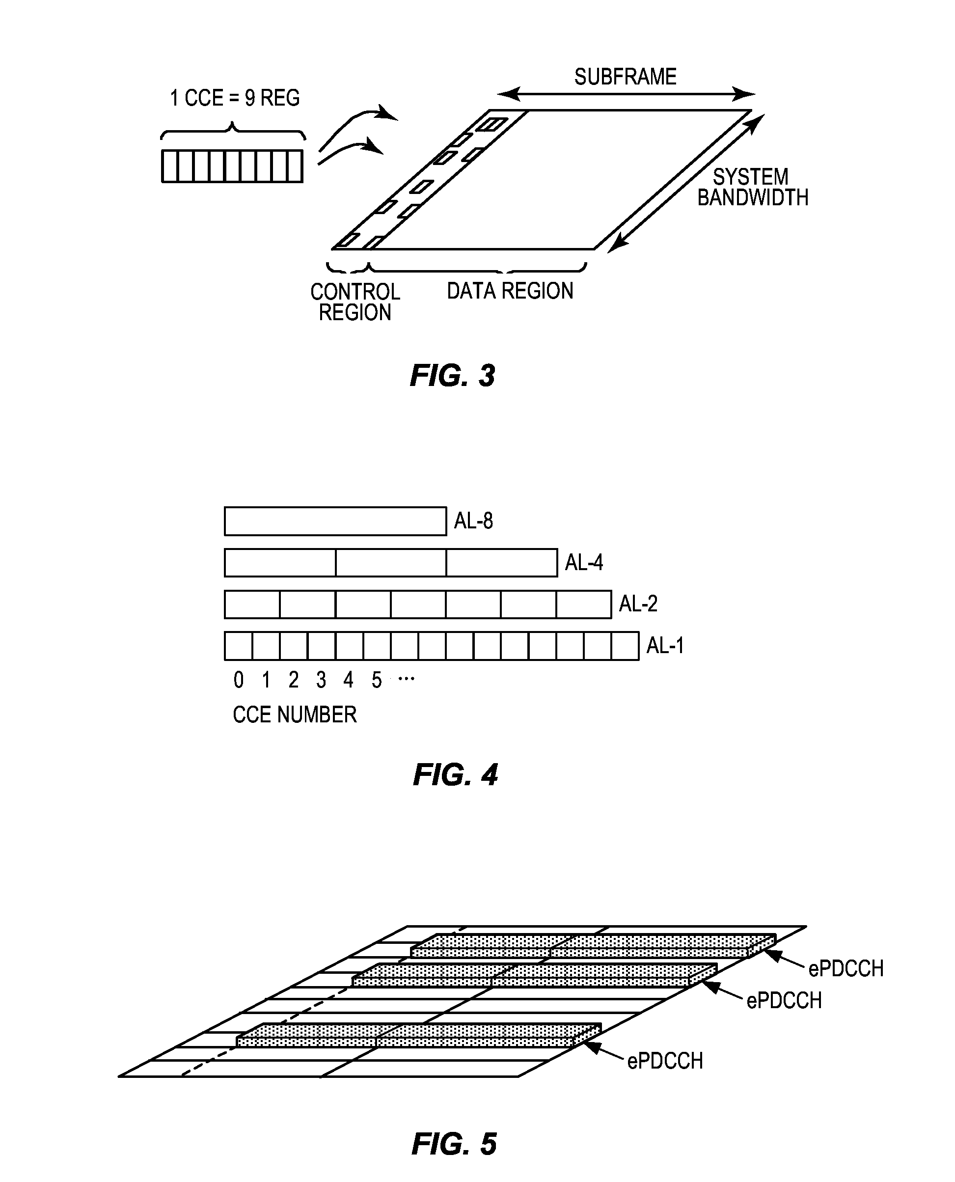
This area splitting and control channel frequency coordination is not possible with the PDCCH, since the PDCCH spans the whole bandwidth.
Further, the PDCCH does not provide possibility to use UE specific precoding since it relies on the use of CRS for demodulation.

Method used


Image

  • ePDCCH Search Space Design
  • ePDCCH Search Space Design
  • ePDCCH Search Space Design

Examples


Embodiment Construction

[0052]In the discussion that follows, specific details of particular embodiments of the presently disclosed techniques and apparatus are set forth for purposes of explanation and not limitation. It will be appreciated by those skilled in the art that other embodiments may be employed apart from these specific details. Furthermore, in some instances detailed descriptions of well-known methods, nodes, interfaces, circuits, and devices are omitted so as not to obscure the description with unnecessary detail. Those skilled in the art will appreciate that the functions described may be implemented in one or in several nodes. Some or all of the functions described may be implemented using hardware circuitry, such as analog and / or discrete logic gates interconnected to perform a specialized function, ASICs, PLAs, etc. Likewise, some or all of the functions may be implemented using software programs and data in conjunction with one or more digital microprocessors or general purpose computer...


PUM


Abstract

Techniques for supporting both localized and frequency-distributed control channel messages in the same enhanced control channel region are disclosed. An example method begins with receiving (2010) a downlink signal comprising an enhanced control region consisting of at least two sets of physical resource block (PRB) pairs. The method continues with the forming (2020) of one or more distributed enhanced control-channel elements (eCCEs) from a first set of PRB pairs by aggregating physical layer building blocks from multiple PRB pairs to form each distributed eCCE. One or more localized eCCEs are formed (2030) from a second set of PRB pairs by aggregating physical layer building blocks such that each of the localized eCCEs is formed from physical layer building blocks from within a single PRB pair of the second set. Control channel message candidates are formed (2050) from the distributed eCCEs and localized eCCEs, respectively, and decoded (2060).

Description

RELATED APPLICATIONS[0001]This application claims the benefit of and priority to U.S. Provisional Application Ser. No. 61 / 679,140, filed 3 Aug. 2012. The entire contents of said U.S. Provisional Application are incorporated herein by reference.TECHNICAL FIELD[0002]The present application is related to control signaling in a wireless communications network.BACKGROUND[0003]The 3rd-Generation Partnership Project (3GPP) has developed a third-generation wireless communications known as Long Term Evolution (LTE) technology, as documented in the specifications for the Evolved Universal Terrestrial Radio Access Network (UTRAN). LTE is a mobile broadband wireless communication technology in which transmissions from base stations (referred to as eNodeBs or eNBs in 3GPP documentation) to mobile stations (referred to as user equipment, or UEs, in 3GPP documentation) are sent using orthogonal frequency division multiplexing (OFDM). OFDM splits the transmitted signal into multiple parallel sub-ca...

Claims


Application Information

Patent Timeline
IPC IPC(8): H04W72/04
CPCH04W72/042H04L5/0007H04L5/0053H04W72/23
Inventor FRENNE, MATTIASFURUSKOG, JOHANKOORAPATY, HAVISHLARSSON, DANIEL
Owner TELEFON AB LM ERICSSON (PUBL)
Learn More