Image processing apparatus and image processing method
- Summary
- Abstract
- Description
- Claims
- Application Information
AI Technical Summary
Benefits of technology
Problems solved by technology
Method used
Image

Examples
first embodiment
1. First Embodiment
[Image Encoding Device]
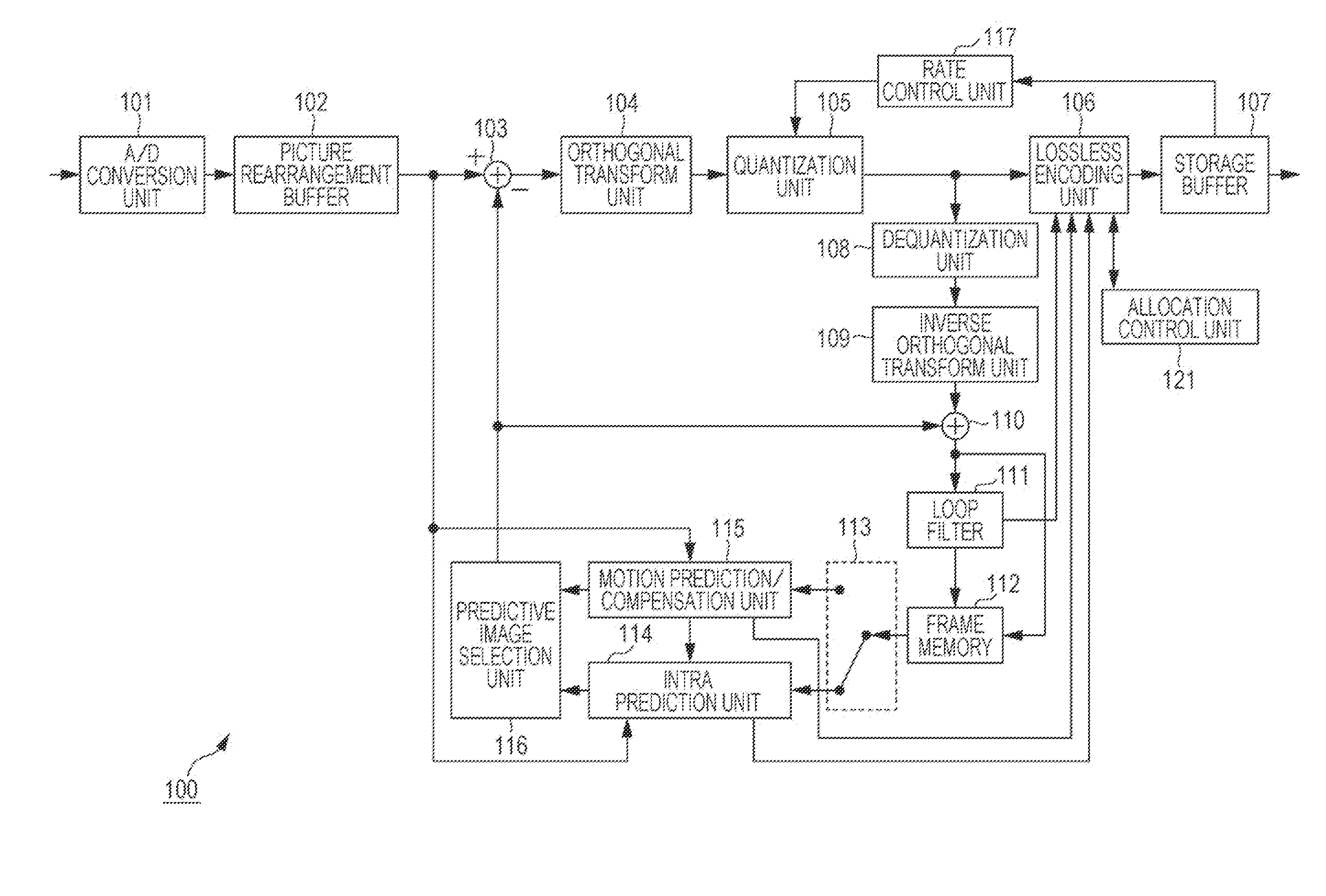
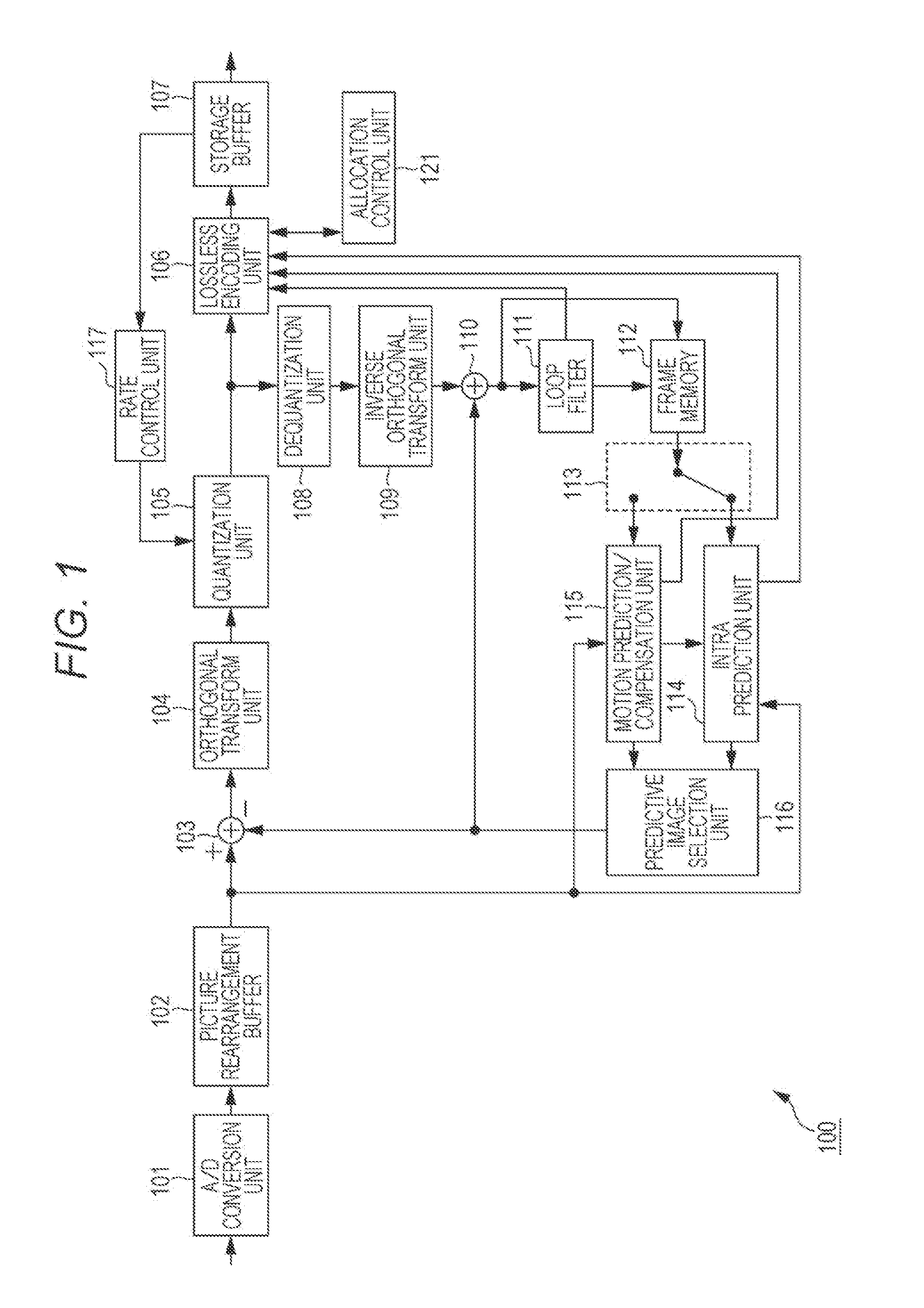
[0079]FIG. 1 is a block diagram illustrating an example of a main configuration of an image encoding device that is an image processing apparatus. An image encoding device 100 illustrated in FIG. 1 encodes image data while employing a prediction process as performed in an encoding system such as H.264 or MPEG (Moving Picture Experts Group) 4 Part 10 (AVC (Advanced Video Coding)).
[0080]As illustrated in FIG. 1, the image encoding device 100 includes an A / D conversion unit 101, a picture rearrangement buffer 102, a calculator 103, an orthogonal transform unit 104, a quantization unit 105, a lossless encoding unit 106, and a storage buffer 107. Further, the image encoding device 100 includes a dequantization unit 108, an inverse orthogonal transform unit 109, a calculator 110, a loop filter 111, a frame memory 112, a selection unit 113, an intra prediction unit 114, a motion prediction / compensation unit 115, a predictive image selection unit 11...
second embodiment
2. Second Embodiment
[Image Decoding Device]
[0236]A process of decoding the data encoded in the aforementioned manner will now be described. FIG. 20 is a block diagram illustrating an example of a main configuration of an image decoding device that is an image processing apparatus corresponding to the image encoding device 100 of FIG. 1.
[0237]An image decoding device 200 illustrated in FIG. 20 decodes encoded data generated by the image encoding device 100 by a decoding method corresponding to the encoding method.
[0238]As illustrated in FIG. 20, the image decoding device 200 includes a storage buffer 201, a lossless decoding unit 202, a dequantization unit 203, an inverse orthogonal transform unit 204, a calculator 205, a loop filter 206, a picture rearrangement buffer 207, and a D / A conversion unit 208. Further, the image decoding device 200 includes a frame memory 209, a selection unit 210, an intra prediction unit 211, a motion prediction / compensation unit 212, and a selection uni...
third embodiment
3. Third Embodiment
[Control of Context Probability Model]
[0305]In the above description, the code number to be allocated to the value of the parameter related to the intra prediction such as mpm_flag, mpm_lr_flag, and intra_dir_mode are controlled in accordance with the size and the shape of the PU for the purpose of improvement of encoding efficiency. However the control of the code amount may be performed by something other than the VLC table.
[0306]That is, the important thing in the present technology is to suppress the code amount using the deviation of the generation probability of a value of a flag related to the MPM or the prediction direction caused by the size and the shape of the PU. Therefore, any process or parameter may be controlled as long as the code amount can be decreased similarly to the examples described in the first and second embodiments.
[0307]For example, the context probability model of the arithmetic encoding may be switched according to the size or the sha...
PUM
 Abstract
Description
Claims
Application Information
 - R&D Engineer
- R&D Manager
- IP Professional
- Industry Leading Data Capabilities
- Powerful AI technology
- Patent DNA Extraction
Browse by: Latest US Patents, China's latest patents, Technical Efficacy Thesaurus, Application Domain, Technology Topic.
© 2024 PatSnap. All rights reserved.Legal|Privacy policy|Modern Slavery Act Transparency Statement|Sitemap