Air cooling design for tail-cone generator installation

Active Publication Date: 2014-03-20
PRATT & WHITNEY CANADA CORP
View PDF11 Cites 28 Cited by
  • Summary
  • Abstract
  • Description
  • Claims
  • Application Information

AI Technical Summary

Problems solved by technology

Still, known cooling systems usually require installation of additional components in the engine system an

Method used


Image

  • Air cooling design for tail-cone generator installation
  • Air cooling design for tail-cone generator installation
  • Air cooling design for tail-cone generator installation

Examples


Embodiment Construction

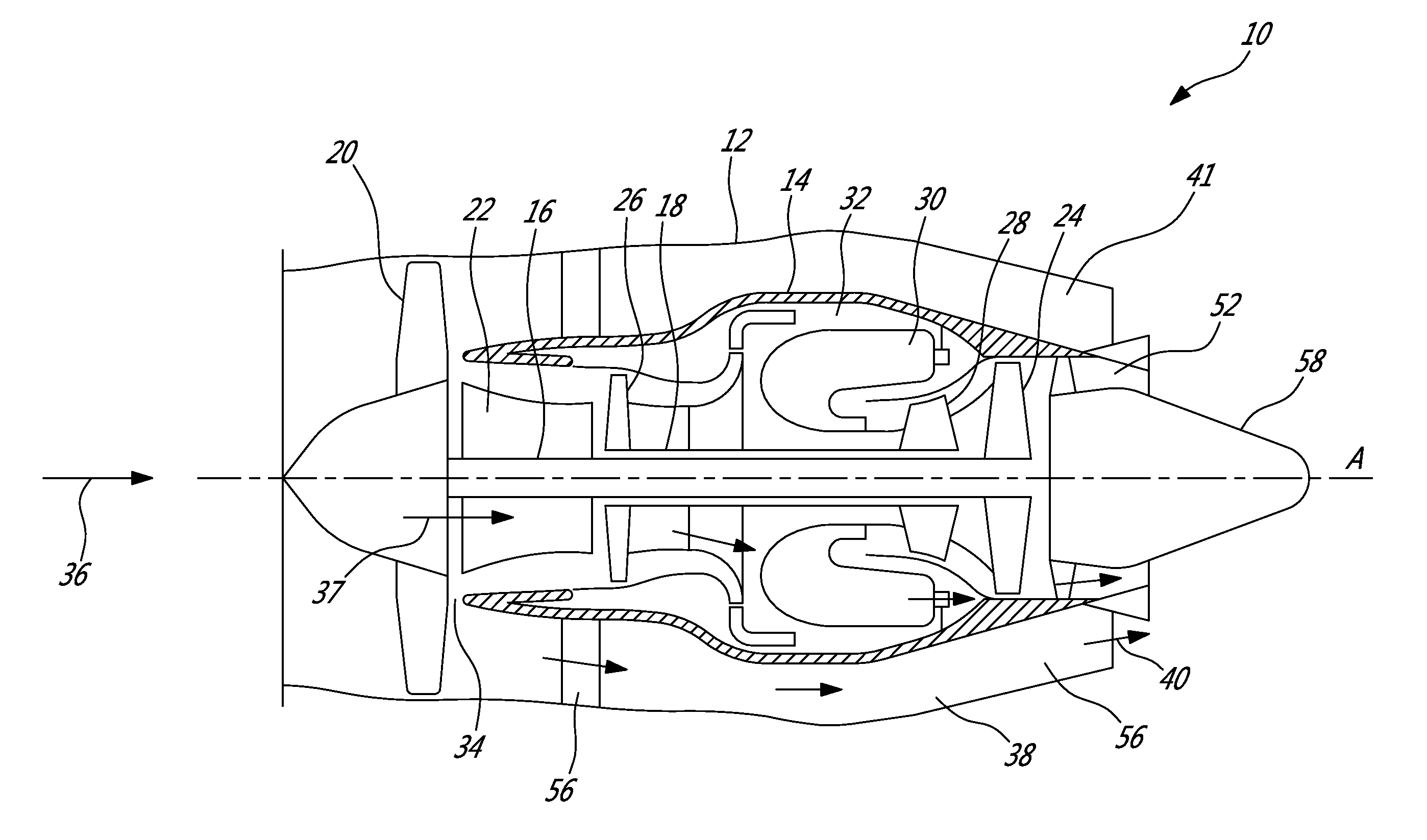
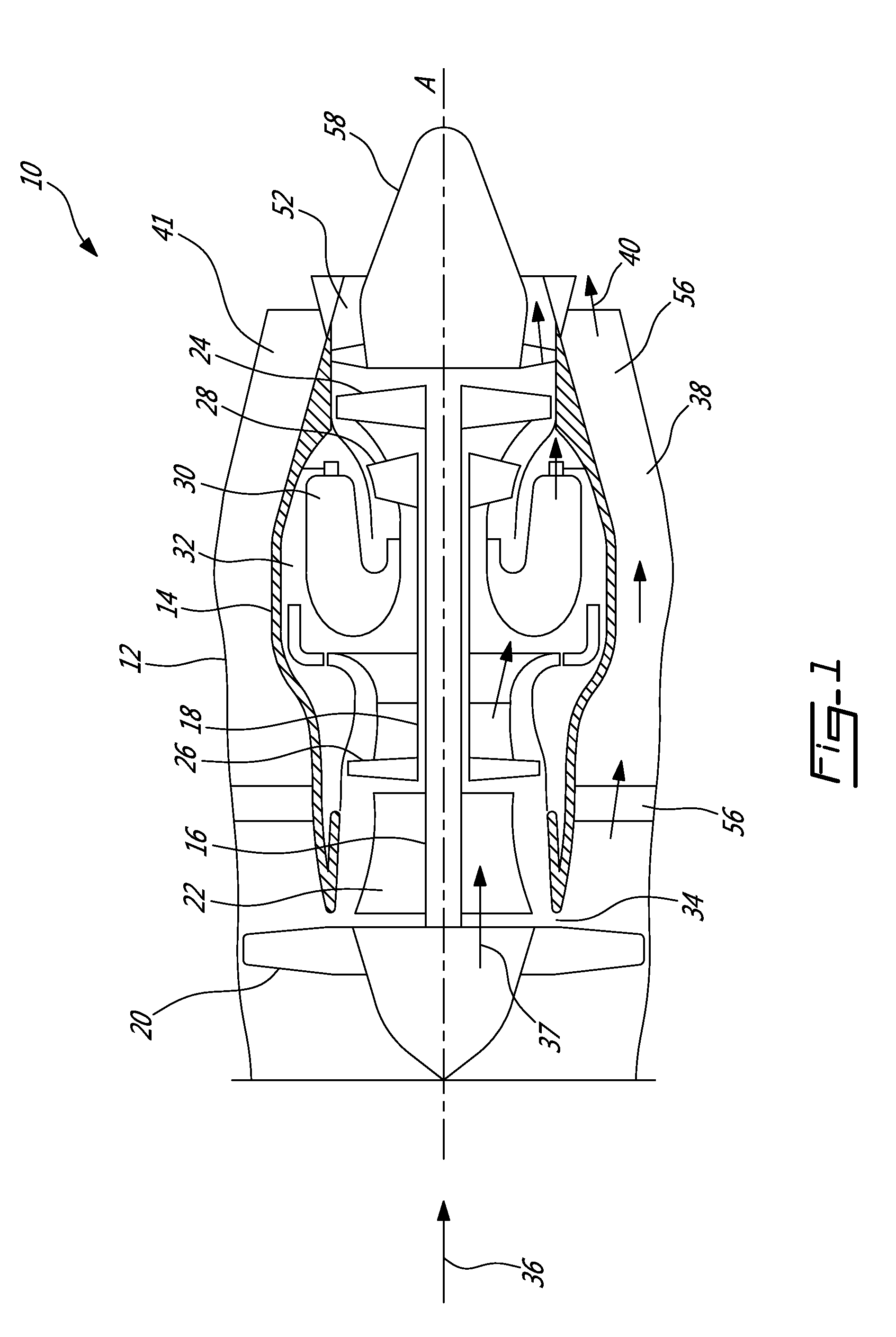
[0014]Referring to FIG. 1, a turbofan gas turbine engine 10 of a type typically provided for use in subsonic flight and presented for illustrative purposes, includes a housing or nacelle 12, a core casing or Turbine Exhaust Case (TEC) 14, a low pressure spool assembly seen generally at 16, and a high pressure spool assembly seen generally at 18. The low pressure spool assembly 16 includes a fan assembly 20, a low pressure compressor assembly 22, and a low pressure turbine assembly 24. The high pressure spool assembly 18 includes a high pressure compressor assembly 26 and a high pressure turbine assembly 28. the core casing 14 surrounds the low and high pressure spool assemblies 16 and 18 in order to define a main fluid path (not shown) therethrough. In the main fluid path, there is provided a combustor 30 to constitute a gas generator section 32.

[0015]The core casing 14 defines with the low pressure compressor assembly 22 a low pressure compressor inlet 34 for receiving a portion of...


PUM


Abstract

A system for cooling a generator mounted in the tail-cone of an engine. The system comprises a fairing, which receives through an inlet thereof air from a bypass duct and directs the bypass air towards a cavity of the tail-cone for cooling the generator. The bypass air is then expelled through an outlet of a support strut positioned in fluid communication with the tail-cone cavity. The fairing inlet and the strut outlet are both positioned in a plane substantially perpendicular to a longitudinal plane of the engine. In this manner, circulation of the bypass air through the fairing, the tail-cone cavity, and the strut may be achieved. The bypass air directed through the fairing further enables cooling of service lines accommodated in the fairing. A lobe mixer is further used to direct the fairing and shield the latter from core exhaust.

Description

TECHNICAL FIELD[0001]The application relates generally to a system and method for cooling a tail-cone mounted generator.BACKGROUND OF THE ART[0002]One or more generators may be positioned in the tail-cone of an engine to provide additional electrical power during normal engine operating conditions as well as emergency situations. However, an engine tail-cone may be quite hot and, thus, in order to ensure proper operation of the generator(s), it is desirable to provide a cooling system to ensure that the temperature of the generator remains acceptable despite being subjected to high temperature flows. Still, known cooling systems usually require installation of additional components in the engine system and may therefore add to the weight and complexity of the engine, in addition to increasing aerodynamic drag.[0003]There is therefore a need for an improved system and method for cooling a tail-cone mounted generator.SUMMARY[0004]In one aspect, there is provided a system for cooling a...

Claims


Application Information

Patent Timeline
IPC IPC(8): F01D25/14
CPCF01D15/10F02C7/12Y02T50/60
Inventor FERCH, GORDONALECU, DANIELLIU, XIAOLIUBARNETT, BARRYSIVALINGAM, DILEEPANFORGIONE, CARMINE
Owner PRATT & WHITNEY CANADA CORP
Why Eureka
Try Eureka