Motor driven two-stage centrifugal air-conditioning compressor

Active Publication Date: 2006-02-14
R & D DYNAMICS
View PDF18 Cites 74 Cited by
  • Summary
  • Abstract
  • Description
  • Claims
  • Application Information

AI Technical Summary

Benefits of technology

[0028]12. Vapor port at second stage to provide economizer action f

Problems solved by technology

While such centrifugal compressor can offer efficient operation, they should not be operated at high rotational speeds.
Low and High Temperature Capabilities: Oil lubricants cannot operate at very high temperatures without breaking down.
At low temperat

Method used


Image

  • Motor driven two-stage centrifugal air-conditioning compressor
  • Motor driven two-stage centrifugal air-conditioning compressor
  • Motor driven two-stage centrifugal air-conditioning compressor

Examples


Embodiment Construction

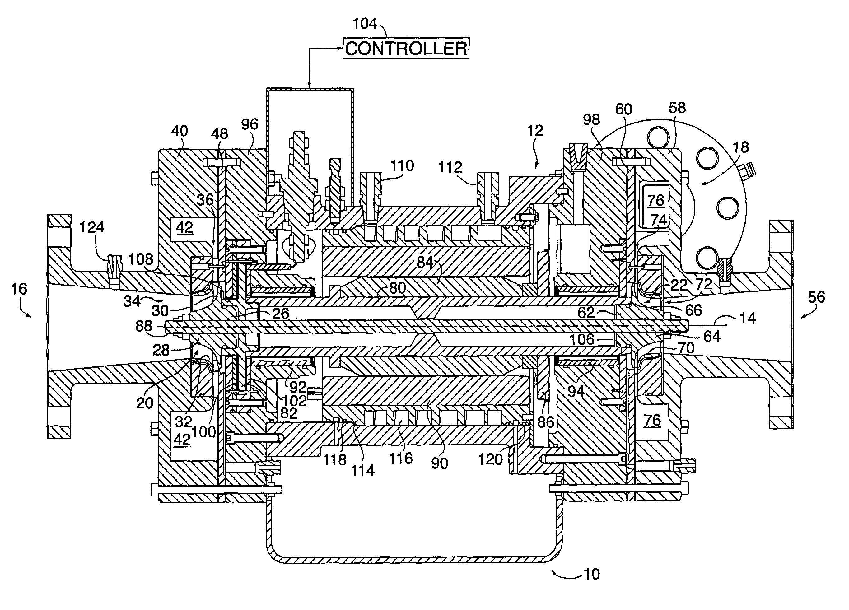
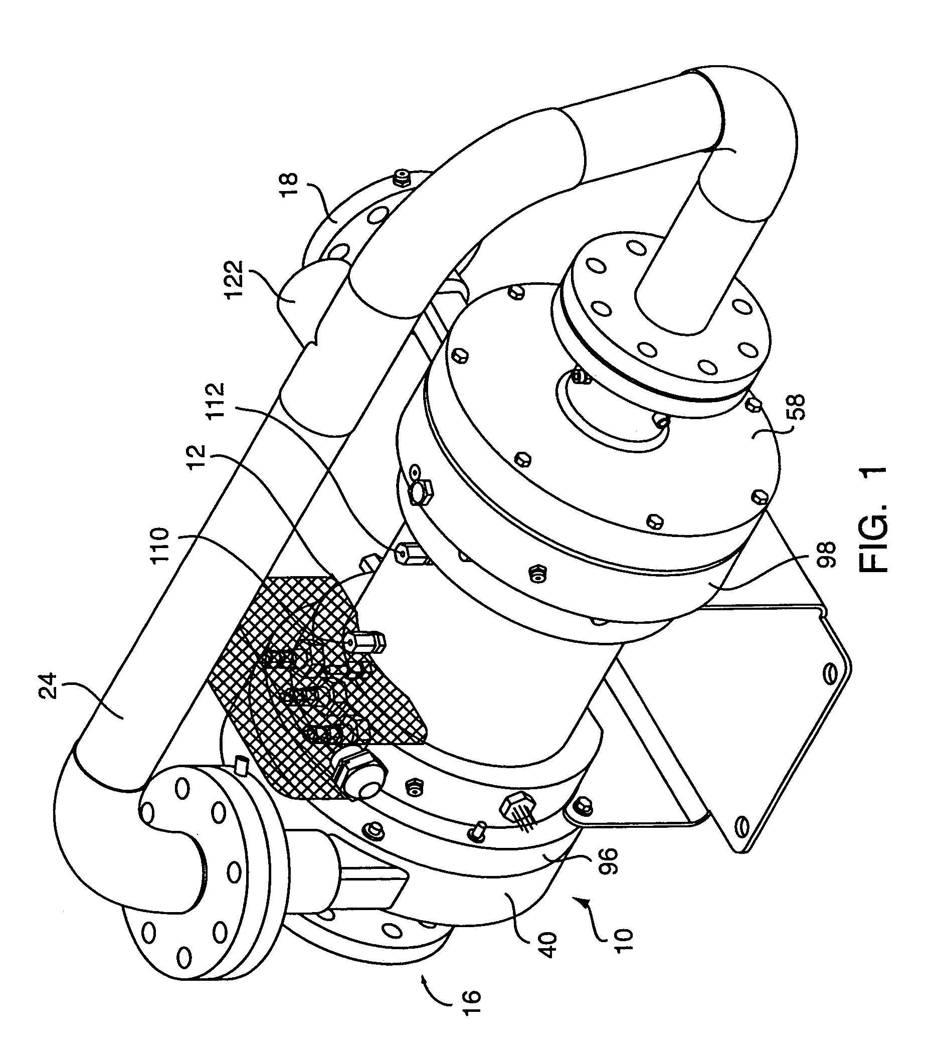
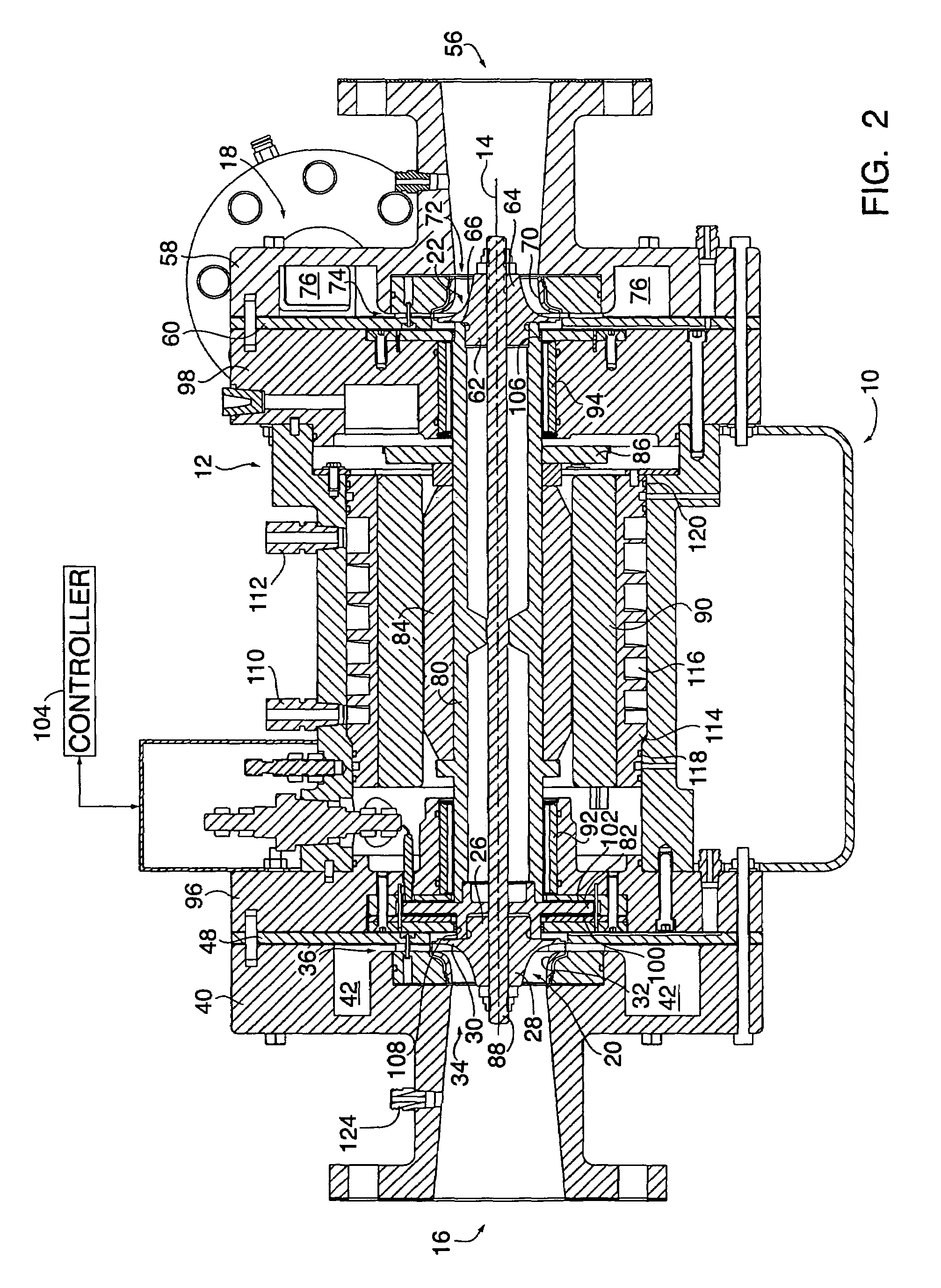
[0040]An external perspective view and cross-section view of a motor driven compressor 10 in accordance with the present invention are shown in FIGS. 1 and 2, respectively. The compressor 10 has a compressor housing 12 which is generally symmetric about a central axis 14. At one end of the housing 12 is an inlet 16 for the refrigerant gas to be compressed, and a discharge outlet 18 for the compressed gas. The compressor 10 shown in FIGS. 1 and 2 is a two-stage centrifugal compressor comprising a first impeller 20 and a second impeller 22 connected in series by a transition pipe 24. The present invention, however, is not limited in this respect, and may be adapted to impellers situated within the compressor in parallel.

[0041]The inlet 16 leads to the first compressor stage which includes the first impeller 20. The first impeller 20 is preferably designed for optimum flow coefficient. As shown more particularly in FIGS. 4 and 5, the first impeller 20 comprises an impeller base 26, an ...


PUM


Abstract

A two-stage compressor for generating necessary pressure differential for air-conditioning applications with air-cooled, water-cooled and evaporative-cooled condensing systems using low-pressure refrigerant, such as R134a, is provided. A rotating assembly is mounted for rotation in a compressor housing and includes a shaft, a thrust bearing disk associated with the shaft to maintain an axial position of the rotating assembly, a motor rotor mounted on the shaft, and first and second impellers mounted for rotation with the shaft. First and second journal bearings are mounted in the compressor housing to support the shaft and maintain radial positioning of the rotating assembly. Volute housings including a spiral-shaped volute are associated with each of the impellers to collect and further discharge gas compressed by the impellers. Diffusers having air-foil shaped vanes are locate in the volute channels adjacent the discharge outlets of the impellers to aide in the discharge of gas from the impellers.

Description

CROSS-REFERENCE TO RELATED APPLICATION[0001]This application claims the benefit of U.S. Provisional Application 60 / 434,837, filed Dec. 19, 2002, which is incorporated herein by reference.FIELD OF THE INVENTION[0002]Air conditioning systems used in homes and commercial buildings consume 36 percent of annually generated primary energy. To reduce energy consumption, high efficiency compressors are required. Commonly, these compressors are motor driven, and compress refrigerant gas into high pressure refrigerant vapor. The present invention relates to conception, design and manufacture of compressors, and more particularly to motor driven compressors in the size ranging from 25 kW to 200 kW. The present invention also relates to associated technologies for compressors, including their integration into packaged air conditioning systems applying air-cooled, water-cooled or evaporative-cooled condensers.BACKGROUND OF THE INVENTION[0003]Historically, compressing refrigerant gas in the compr...

Claims


Application Information

Patent Timeline
IPC IPC(8): F04B17/03F04D17/12F04D25/06F04D29/28F04D29/58F04D29/62
CPCF04D17/12F04D25/0606F04D29/624F04D29/584F04D29/284F04D29/057F04D29/5806
Inventor AGRAWAL, GIRIDHARI L.JORGENSEN, NIELS A.
Owner R & D DYNAMICS
Why Eureka
Try Eureka