Battery System Control Method

a battery system and control method technology, applied in the direction of secondary cell servicing/maintenance, electrochemical generators, transportation and packaging, etc., can solve the problems of difficult to apply balance control methods, difficult to interconnection to battery controllers b, etc., to reduce the amount of data, reduce the size of board circuits, and prevent a large amount of cell data

Inactive Publication Date: 2014-03-20
HITACHI LTD
View PDF2 Cites 21 Cited by
  • Summary
  • Abstract
  • Description
  • Claims
  • Application Information

AI Technical Summary

Benefits of technology

[0009]In order to solve the above problems, according to an aspect of the invention, in a battery system in which plural battery cells are connected to each other in series, in parallel or in series-parallel to form an assembled battery; each assembled battery is connected to a first-ranking controller that monitors and controls battery cells that belong to the assembled battery; the first-ranking controller includes a cell voltage measuring unit configured to individually detect an inter-terminal voltage of the battery cell, a cell balance unit configured to individually discharge the battery cells that belong to the assembled battery, a communication unit configured to transmit a minimum value or an average value of cell voltages to a higher second-ranking controller as a representative value, and a control unit configured to receive a discharge instruction from the higher second-ranking controller and giving the discharge instruction to the cell balance unit; the second-ranking controller includes a communication unit configured to obtain the representative values of the voltages from the first-ranking controllers and transmitting a minimum value or an average value thereof as a representative value to a higher third-ranking controller, and a control unit configured to receive a discharge instruction from the higher third-ranking controller and giving the discharge instruction to the lower second-ranking controllers; and the third-ranking controller includes a communication unit configured to obtain the representative values of the voltages from the second-ranking controllers and transmitting a minimum value or an average value thereof to a monitor and control device such as a personal computer as a representative value, and control unit configured to receive a discharge instruction from the higher-ranking monitor and control device and giving the discharge instruction to the lower second-ranking controllers, cell voltage information is transmitted to a higher-ranking controller in the hierarchical battery system, a discharging amount is calculated for each controller, and the discharge instruction is transmitted to the lowest-ranking controller to control a discharge circuit, thereby preventing a voltage variation between the cells and a voltage variation between the controllers.
[0010]According to this configuration, by providing hierarchical monitor and control of a battery system, it is possible to equalize cell voltages of the entire battery system by a discharge circuit that is connected in parallel to cells. Thus, it is not necessary to provide an individual balance control circuit at each rank, and to provide a circuit that operates at a high voltage.
[0011]Further, by providing hierarchical monitor of cell voltages, it is possible to transmit a representative value such as a minimum value or an average value of the cell voltages, to thereby reduce the amount of data. Thus, it is possible to prevent a large amount of cell data from being concentrated on the highest-ranking controller.
[0012]Further, since a controller at the second or higher rank does not directly measure battery cells but performs only communication and control, it is possible to extend the ranks using controllers having the same function. Thus, it is easy to make a greater capacity of the battery system.

Problems solved by technology

Further, since a voltage corresponding to an assembled battery voltage is applied to the module discharge circuit 206 that is connected in parallel to the assembled batteries, it is necessary to secure an insulation distance with peripheral circuits, which makes it difficult to reduce the size of a board circuit.
Thus, for example, a communication speed necessary in a large-scale battery system handling multiple assembled batteries is increased and interconnection to the battery controller 208 becomes difficult, which makes it difficult to apply the balance control method.

Method used


Image

  • Battery System Control Method
  • Battery System Control Method
  • Battery System Control Method

Examples


example 1

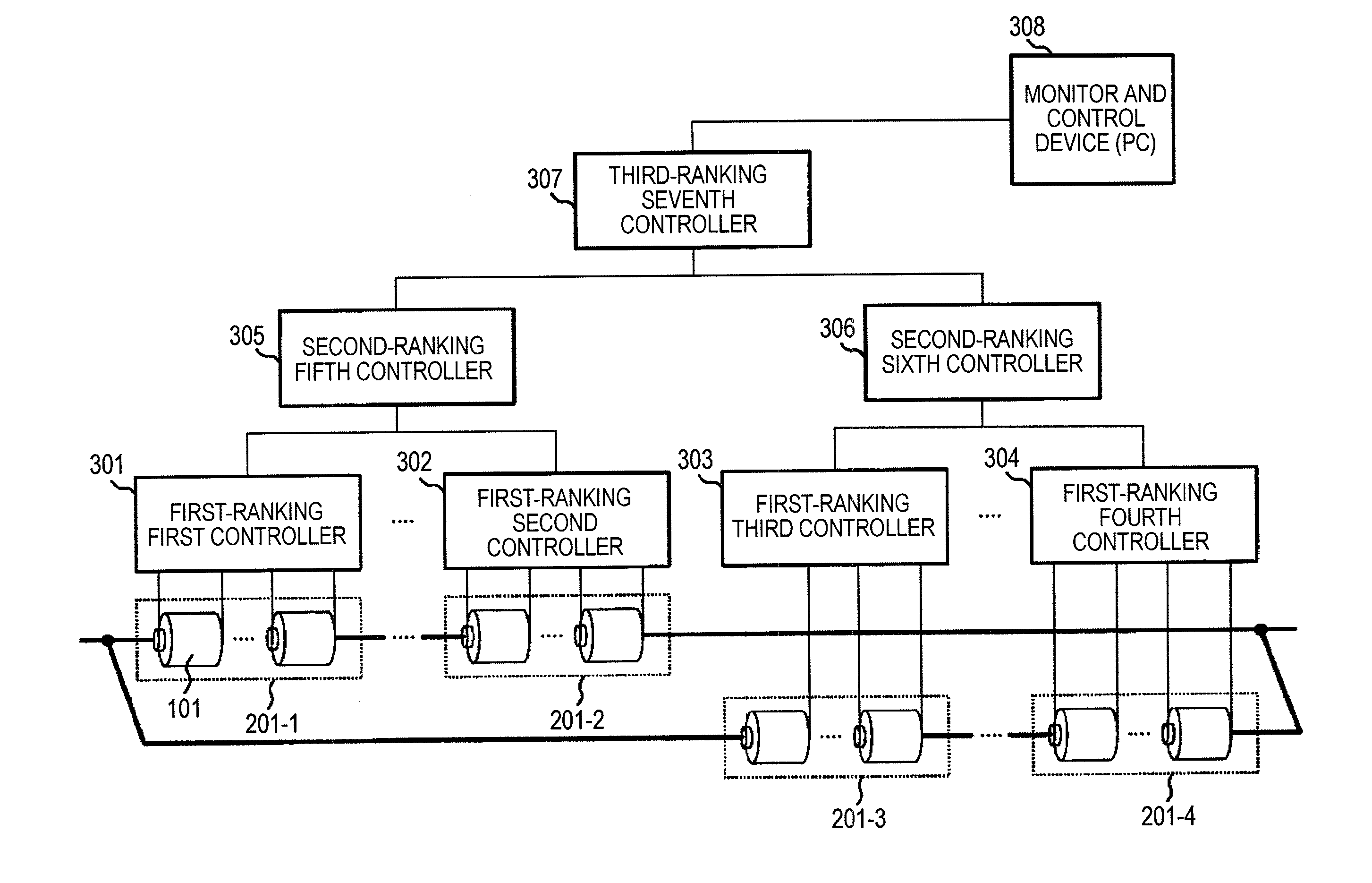
[0026]FIG. 3 is a conceptual diagram of a battery system that includes three ranks, for description of a hierarchical control battery system shown in Example 1.

[0027]Plural battery cells 101 are connected to each other in series, in parallel, or in series-parallel, to form first to fourth assembled batteries 201-1 to 201-4. In order to equalize voltages between the battery cells 101, first-ranking controllers 301 to 304 are respectively connected to the first to fourth assembled batteries 201-1 to 201-4 to monitor a voltage of each battery cell 101, thereby performing a balance control. A second-ranking controller obtains voltage information from the plural first-ranking controllers, and gives a balance control instruction to the first-ranking controllers. A third-ranking controller obtains voltage information from the plural second-ranking controllers, and gives a balance control instruction to the second-ranking controllers.

[0028]A monitor and control device 308 that is capable of...

example 2

[0043]A balance control method that is applicable to the configuration of Example 1 will be described.

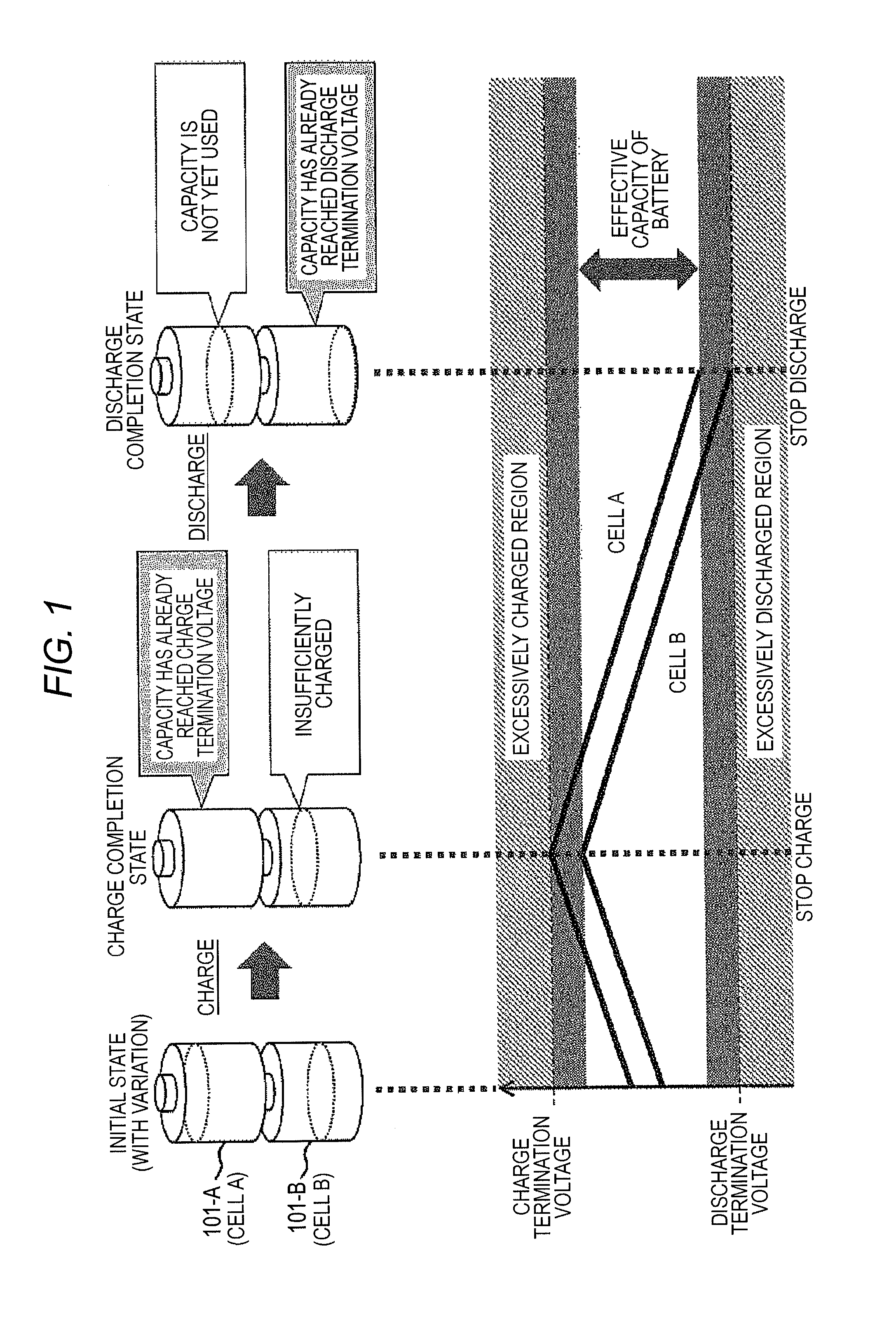
[0044]In general, in a battery system, it is necessary to inform the degree of a current charging rate to a user. Even in a case where variation is present in a charged state of a battery cell, it is important to inform a current average charging rate of the battery system in view of a residual charge capacity and a residual discharge capacity. Since the average charging rate of the battery system may be calculated from an average voltage of the entire cells, a controller of a hierarchical control battery system transmits an average voltage of a cell group managed by each controller to a higher-ranking controller.

[0045]In Example 2, a balance control in a case where an average voltage of cells is transmitted to a higher rank, and a discharge instruction measuring method will be described. FIG. 6 is a flowchart of a balance control of Example 2.

[0046]When an nth-ranking controller ma...

example 3

[0054]A balance control method that is applicable to the configuration of Example 1 will be described.

[0055]In Example 3, a control method in which a minimum voltage value of representative voltage values collected from a lower rank at the same time when an average voltage of cells is transmitted to a higher rank is used as a reference voltage of a balance control, and a calculation method of a discharge instruction will be described. FIG. 8 is a flowchart of a balance control of Example 3.

[0056]When the nth-ranking controller manages m pieces of (n−1)th-ranking controllers, the nth-ranking controller obtains m pieces of representative voltage information ((V(n-1, 1), V(n-1, 2), . . . , V(n-1, m)) about the (n−1)th rank (S801). In a case where a controller belongs to the first rank (n=1), a voltage obtained from the (n−1)th rank means a cell voltage.

[0057]Here, a minimum value of the m pieces of representative voltage information collected from the (n−1)th rank is set as an nth-rank...


PUM

PropertyMeasurementUnit
inter-terminal voltageaaaaaaaaaa
thresholdaaaaaaaaaa
threshold valueaaaaaaaaaa

Abstract

The entire voltage of batteries is transmitted to a higher-ranking controller as information. The higher-ranking controller gives a discharge instruction or the like to a lower-ranking controller having a voltage higher than those of the other controllers. Thus, voltage variation of the respective batteries is balanced.

Description

CROSS-REFERENCE TO RELATED APPLICATION[0001]This application claims the priority of Japanese Patent Application No. 2012-202217 filed Sep. 14, 2012, which is incorporated herein by reference in its entirety.BACKGROUND OF THE INVENTION[0002]1. Field of the Invention[0003]The present invention relates to a control method for a battery system that includes plural batteries, and particularly, to a battery system control method for equalization of a charged state between batteries.[0004]2. Background Art[0005]Installation of a large-scale battery system in a system or a power plant has been studied from the viewpoint of stabilization of an electric power system or a smart grid. In order to obtain output and capacity necessary for a battery system, plural battery cells are connected to each other in series and in parallel. When the battery system is charged or discharged, the same electric current flows in the respective battery cells that are connected in series. Thus, if all the battery...

Claims


Application Information

Patent Timeline
Patent Type & Authority Applications(United States)
IPC IPC(8): H01M10/44H02J7/02
CPCH01M10/441H02J7/0016H01M10/482H01M2010/4271H01M2010/4278H01M10/425Y02E60/10
Inventor TAKEUCHI, TAKASHIMIURA, MASAHIROTERADA, TAKAHIDE
Owner HITACHI LTD
Why Eureka
Try Eureka