Engine starting system and engine starting method
a technology of engine starting system and engine, which is applied in the direction of engine-driven generators, machines/engines, process and machine control, etc., can solve the problems of excessive amount of vaporized fuel in the fuel tank and the like trapped in the canister, the time that the engine continues to be stopped, and the engine will almost never be driven, etc., to achieve the effect of suppressing the decrease in fuel efficiency
- Summary
- Abstract
- Description
- Claims
- Application Information
AI Technical Summary
Benefits of technology
Problems solved by technology
Method used
Image
Examples
first example embodiment
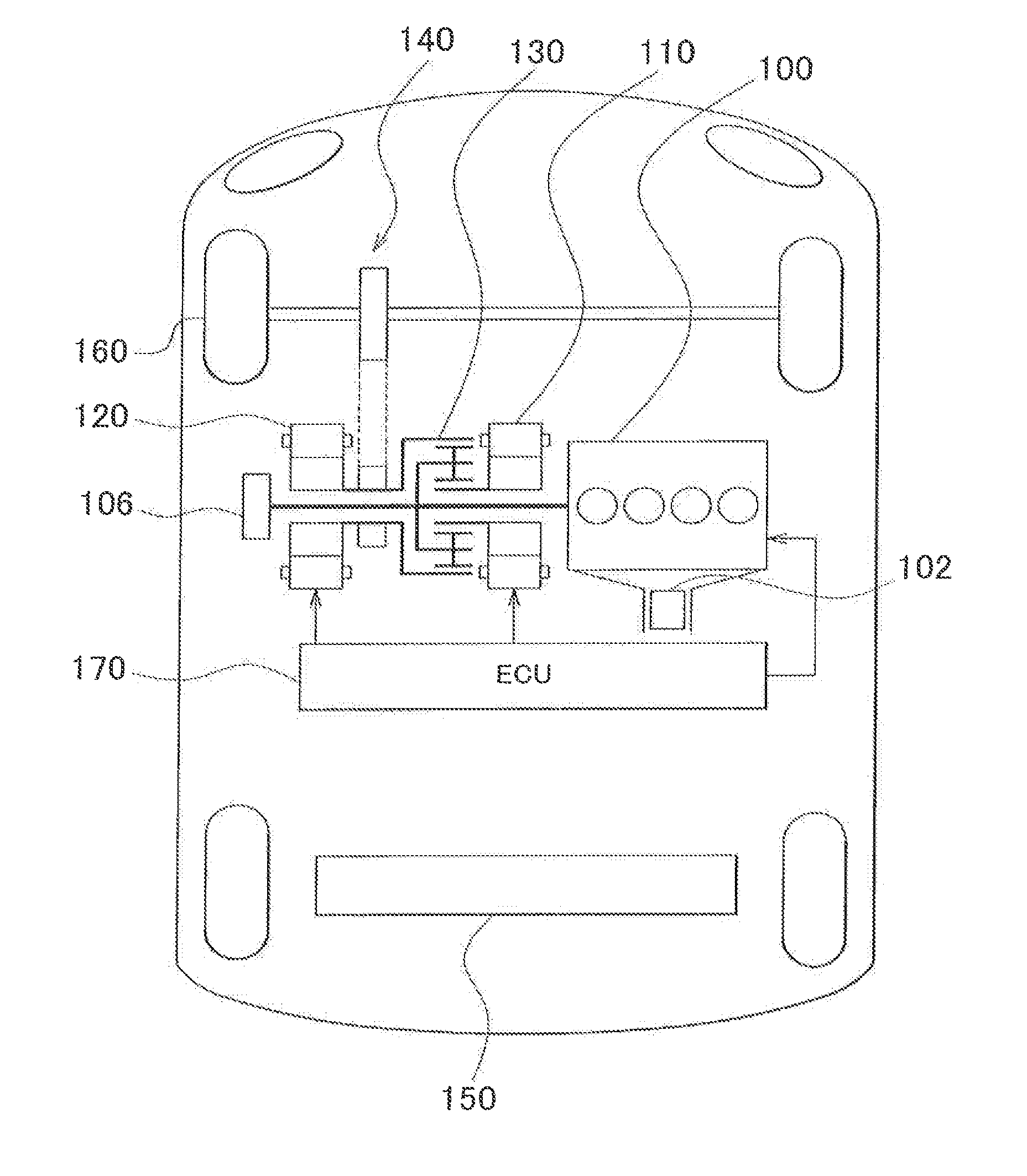
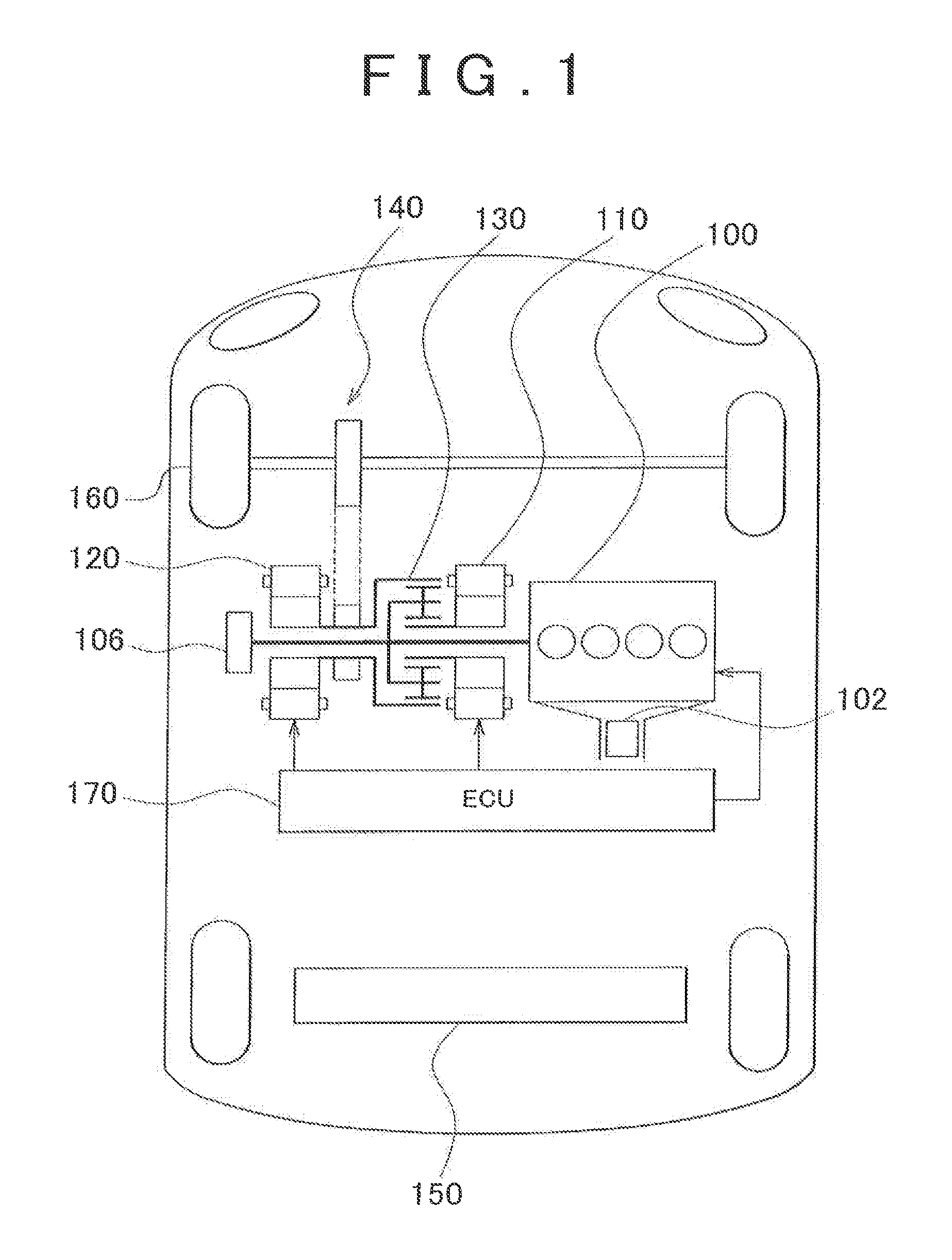
[0034]A plug-in hybrid vehicle is provided with an engine 100, a first motor-generator 110, a second motor-generator 120, a power split device 130, a reduction gear 140, and a battery 150, as shown in FIG. 1.
[0035]The engine 100, the first motor-generator 110, the second motor-generator 120, and the battery 150 are all controlled by an ECU (Electronic Control Unit) 170. The ECU 170 may also be divided into a plurality of ECUs.
[0036]This vehicle runs using torque from at least one of the engine 100 or the second motor-generator 120. That is, one or both of the engine 100 and the second motor-generator 120 is automatically selected as the drive source according to the operating state.
[0037]For example, when the accelerator operation amount is small or when the vehicle speed is low or the like, the plug-in hybrid vehicle runs using only the second motor-generator 120 as the drive source. in this case, the engine 100 is stopped.
[0038]Also, when the accelerator operation amount is large,...
second example embodiment
[0119]Hereinafter, a second example embodiment of the invention will be described. In the second example embodiment, the engine 100 is driven in an operating state (such as the output torque and rotation speed) in which the efficiency of the engine 100 is equal to or greater than a preset efficiency. The other aspects of the second example embodiment are the same as those of the first example embodiment, so detailed descriptions thereof will not be repeated here.
[0120]A routine executed by the ECU 170 will now be described with reference to FIG. 9. The following routine is executed when a hybrid system is turned on, for example. This routine may be realized by software or by hardware. Steps in this routine that are the same as those in the routine of the first example embodiment will be denoted by the same step numbers, so detailed descriptions thereof will not be repeated here.
[0121]In step S200, the ECU 170 estimates the efficiency of the engine 100 according to the estimated engi...
third example embodiment
[0124]Hereinafter, a third example embodiment of the invention will be described. In the third example embodiment, the engine 100 is driven in an operating state. in which the efficiency of a hybrid system that includes the engine 100, the first motor-generator 110, and the second motor-generator 120 is equal to or greater than a preset efficiency. The other aspects of the third example embodiment are the same as those of the first or second example embodiment, so detailed descriptions thereof will not be repeated here.
[0125]A routine executed by the ECU 170 will now be described with reference to FIG. 11. The following routine is executed when the hybrid system is turned on, for example. This routine may be realized by software or by hardware. Steps in this routine that are the same as those in the routine of the first example embodiment will be denoted by the same step numbers, so detailed descriptions thereof will not be repeated here.
[0126]In step S300, the ECU 170 estimates the...
PUM
 Abstract
Description
Claims
Application Information
 - R&D
- Intellectual Property
- Life Sciences
- Materials
- Tech Scout
- Unparalleled Data Quality
- Higher Quality Content
- 60% Fewer Hallucinations
Browse by: Latest US Patents, China's latest patents, Technical Efficacy Thesaurus, Application Domain, Technology Topic, Popular Technical Reports.
© 2025 PatSnap. All rights reserved.Legal|Privacy policy|Modern Slavery Act Transparency Statement|Sitemap|About US| Contact US: help@patsnap.com


