Wheel and tire assembly and method of assembly

a technology of wheels and tires, which is applied in the direction of mechanical equipment, manufacturing tools, transportation and packaging, etc., can solve the problems of inconvenient or difficult reaching the tires to perform maintenance and repairs, damage to the tires, and equipment mounted on the tires

Active Publication Date: 2014-03-27
LINDSAY CORP
View PDF12 Cites 8 Cited by
  • Summary
  • Abstract
  • Description
  • Claims
  • Application Information

AI Technical Summary

Benefits of technology

[0008]Embodiments of the present invention solve the above-described problems by providing a wheel and tire assembly including an airless tire that presents certain performance characteristic of a pneumatic tire. In particular, the wheel assembly is configured such that the tire flexes inwardly in response to ground engaging pressure thereby minimizing ground penetration and soil disturbance.
[0012]A method of assembling a wheel assembly in accordance with yet another embodiment of the invention comprises placing a first portion of a wheel in engagement with an airless tire such that a first plurality of drive lugs of the tire engage a plurality of receptacles of the first portion of the wheel, placing a second portion of a wheel in engagement with the airless tire such that a second plurality of drive lugs of the tire engage a plurality of receptacles of the second portion of the wheel, and removably fastening the first portion of the wheel to the second portion of the wheel.

Problems solved by technology

Because irrigation systems and similar agricultural equipment are typically used in fields or other remote locations, monitoring the tires for problems and reaching the tires to perform maintenance and repairs can be inconvenient or difficult.
If a tire loses air pressure and is not repaired in a timely manner, damage to the tire, to the equipment mounted on the tire, or both may result.
While this approach addresses most of the problems of tire maintenance, repair and replacement, it presents other challenges.
Tireless wheels, for example, are rigid and experience greater ground penetration than a pneumatic tire, thereby creating ruts or otherwise disturbing the ground more than a pneumatic tire.
The problems associated with ground disturbance are compounded with the use of irrigation systems, where the ground is moist and more susceptible to disturbance rutting, and where the irrigation system wheels may traverse the same path multiple times. Similar problems exist for tractors, automobiles, and other vehicles that typically use pneumatic tires.

Method used


Image

  • Wheel and tire assembly and method of assembly
  • Wheel and tire assembly and method of assembly
  • Wheel and tire assembly and method of assembly

Examples


first embodiment

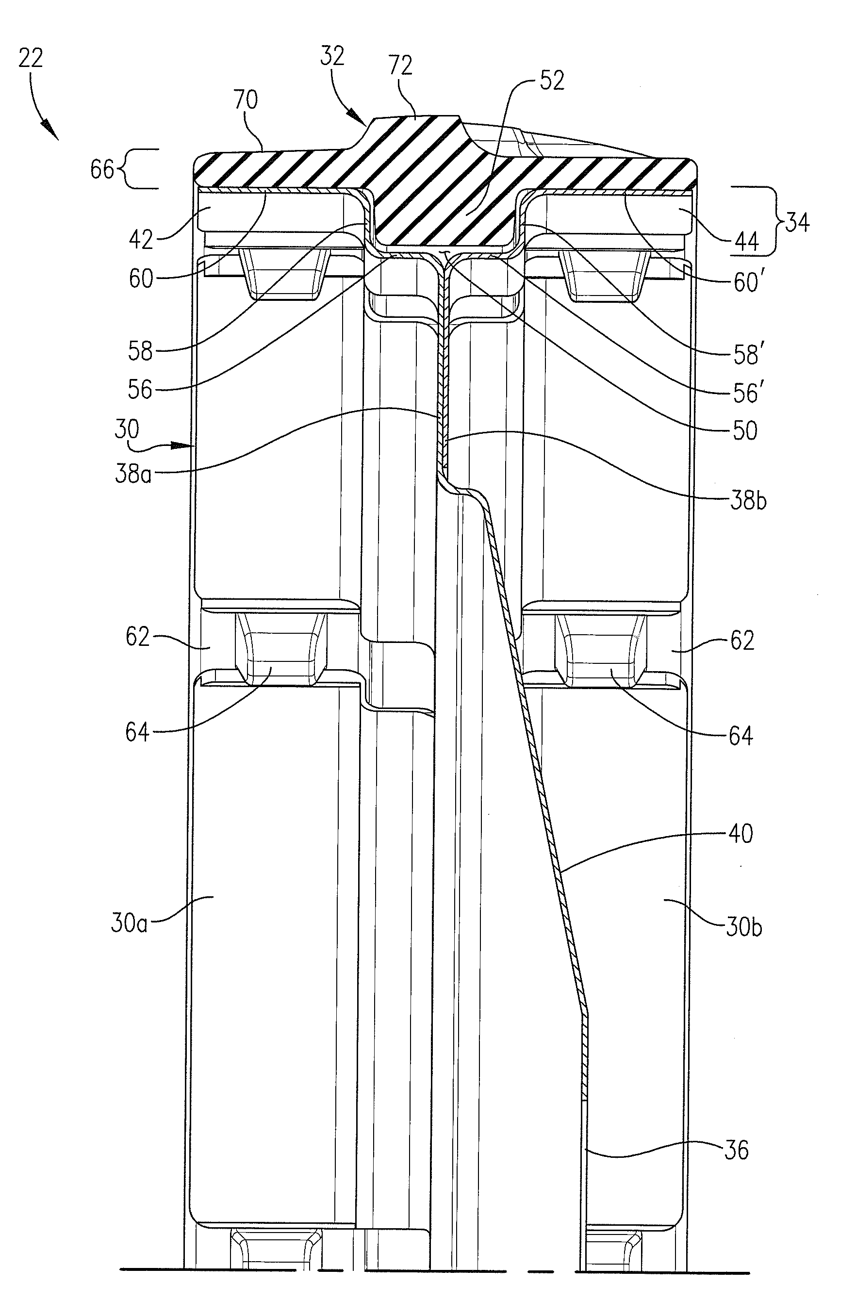
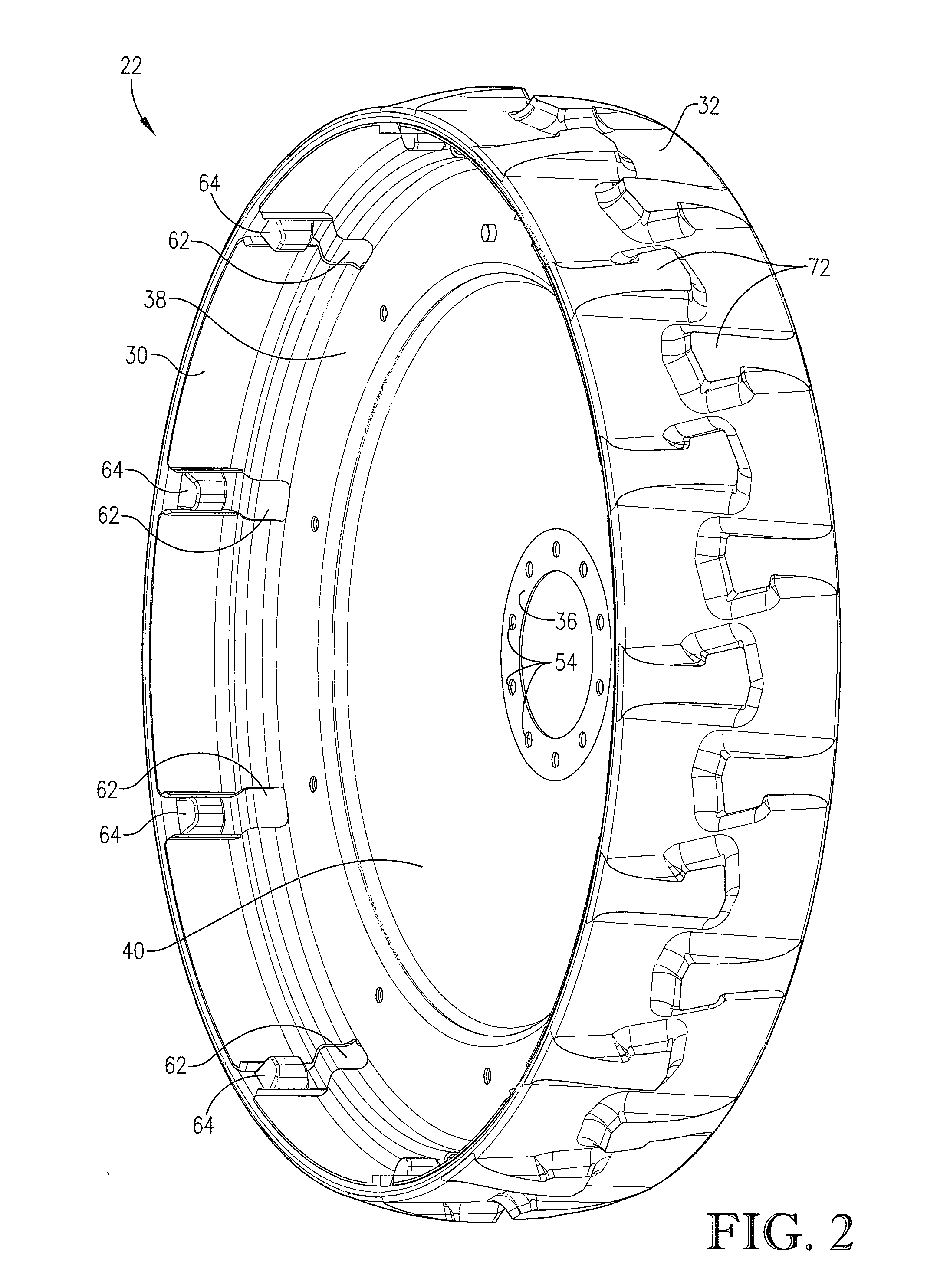
[0047]Referring now to FIGS. 2-11, a wheel assembly 22 constructed in accordance with the invention is illustrated. The wheel assembly 22 broadly comprises a rigid wheel 30 and a flexible airless tire 14 mounted on the wheel 30. The wheel 30 comprises a tire engaging portion 34, a hub 36, a flange portion 38, and a web portion 40 interconnecting the hub 36 and the flange portion 38. The tire engaging portion 34 is configured to engage and support the tire 32 and to allow a portion of the tire 32 to flex radially inwardly in response to ground engaging pressure, thus presenting some performance characteristics of a pneumatic tire and minimizing ground penetration during use. More particularly, the tire engaging portion 34 presents a pair of axially spaced rim portions 42, 44 configured to engage and support corresponding sides of the tire 32. Each of the rim portions 42, 44 presents a radially outer surface 46, 48 that extends substantially entirely around the circumference of the wh...

second embodiment

[0067]A wheel assembly 100 constructed in accordance with the invention is illustrated in FIGS. 12-16. The wheel assembly 100 may include the wheel 30 and an airless tire 102 identical to the tire 32 described above in form and function, except that the tire 102 does not have a structure similar to the flange 52 extending radially inwardly from a body 104 of the tire 102. Rather, the channel 50 of the wheel 30 presents an open space under the tire 102 such that the tire 102 deflects into the channel when subject to ground-engaging pressure, as illustrated in FIG. 13.

[0068]The tire 102 may include one or more tension elements 108, as illustrated in FIGS. 15 and 16. Each of the tension elements 108 may be similar or identical to the tension elements 74 described above in size, shape and composition. The tire 102 may include a pair of tension elements 108 embedded in opposing axial sides of the tire 102, as illustrated in FIG. 15, or may include a single tension member 108 embedded in ...

third embodiment

[0069]A wheel assembly 200 constructed in accordance with the invention is illustrated in FIGS. 17 and 18. The wheel assembly 200 includes a wheel 202 and an airless tire 204. The wheel 202 is similar to the wheel 30 described above, except that the wheel 202 includes a tire engaging portion 206 that does not have a channel but rather presents a substantially uniform, transversely flat outer rim wall 208 comprising two sides, 208a and 208b. The rim wall 208 presents an outer surface 210 that is substantially transversely flat from a first edge 212 of the wheel 202 to a second edge 214 of the wheel 202.

[0070]The wheel comprises two axial sides 202a, 202b. A first side 202a includes a first half 208a of the rim wall, a flange 216a, a central hub 218, and a web portion 220 that extends from the hub 218 to the flange 216a. The flange 216a is similar to the flange 20a described above in both form and function and, in the illustrated embodiment, is substantially perpendicular to the axis ...


PUM

PropertyMeasurementUnit
thickaaaaaaaaaa
thickaaaaaaaaaa
thickaaaaaaaaaa

Abstract

A wheel assembly includes a rigid wheel and an airless tire. The wheel includes a cylindrical rim portion that is parallel with an axis of rotation of the wheel and includes a transversely flat outer surface corresponding to at least eighty percent of the total width of the rim portion. The tire is mounted on the rim portion of the wheel and includes a cylindrical tire body presenting a transversely flat inner surface that engages the outer surface of the wheel. A plurality of traction lugs are spaced circumferentially around the tire and extend radially outwardly from the tire body. A plurality of drive lugs are spaced circumferentially around the tire, extend radially inwardly from the tire body and engage corresponding receptacles on the rim portion of the wheel.

Description

BACKGROUND[0001]1. Field[0002]Embodiments of the present invention relate to wheel and tire assemblies. More particularly, embodiments of the present invention relate to wheel and tire assemblies including airless tires presenting certain performance characteristics of pneumatic tires.[0003]2. Related Art[0004]Mobile irrigation systems include elevated water conduits supported by mobile towers. Such mobile towers are mounted on wheels that propel the towers along the ground to be irrigated. The wheels typically include pneumatic tires that require periodic maintenance, including adjusting air pressure, repairing tires that develop holes or other damage, and replacing worn or damaged tires that are beyond repair.[0005]Because irrigation systems and similar agricultural equipment are typically used in fields or other remote locations, monitoring the tires for problems and reaching the tires to perform maintenance and repairs can be inconvenient or difficult. If a tire loses air pressu...

Claims


Application Information

Patent Timeline
Patent Type & Authority Applications(United States)
IPC IPC(8): B60C7/24B23P11/00
CPCB60C11/0311B60C7/22Y10T152/10297Y10T29/49494B60C7/24B60C7/101B60B25/002
Inventor KORUS, THOMAS J.
Owner LINDSAY CORP
Why Eureka
Try Eureka