Photovoltaic Arrays, Methods and Kits Therefor

a photovoltaic array and photovoltaic technology, applied in photovoltaic supports, pv power plants, sustainable buildings, etc., can solve the problems of undesirable aesthetic appearance and increasing cost of fossil fuels, and achieve streamlined aesthetic appearance, efficient covering and closing, and avoiding penetration of roof decks

Inactive Publication Date: 2014-07-03
CERTAINTEED CORP
View PDF2 Cites 8 Cited by
  • Summary
  • Abstract
  • Description
  • Claims
  • Application Information

AI Technical Summary

Benefits of technology

[0010]Various aspects of the present invention are directed to roofing-integrated photovoltaic arrays and configurations for efficiently covering and closing electrical connection systems of the arrays with economical use of materials while providing a streamlined aesthetic appearance and minimizing or avoiding penetrations of the roof deck. In certain aspects, photovoltaic arrays of the present invention include matched sets of photovoltaic modules, the modules having electrical elements (i.e., any feature protruding from or formed in the face of module and used in electrical connections, e.g., connectors, junction boxes, sockets) located such that when the modules are arranged in a laterally offset arrangement of courses in a photovoltaic array, the electrical connection points align spatially, thus minimizing the area of exposed wiring system in need of covering by a wiring raceway cover or conduit.

Problems solved by technology

First, fossil fuels have become increasingly expensive due to increasing scarcity and unrest in areas rich in petroleum deposits.
Second, there exists overwhelming concern about the effects of the combustion of fossil fuels on the environment due to factors such as air pollution (from NOx, hydrocarbons and ozone) and global warming (from CO2).
Such wide raceways can require a relatively large amount of material, and can cause undesirable aesthetic appearance.

Method used


Image

  • Photovoltaic Arrays, Methods and Kits Therefor
  • Photovoltaic Arrays, Methods and Kits Therefor
  • Photovoltaic Arrays, Methods and Kits Therefor

Examples


Embodiment Construction

[0081]The field of roofing-integrated photovoltaic products has been advancing in recent years. U.S. Pat. No. 5,575,861 and U.S. Pat. No. 5,437,735; and U.S. Patent Application Publications nos. 2009 / 0159118 and 2009 / 0178350 each of which is hereby incorporated herein by reference in its entirety, disclose roofing products and systems where a roof is equipped with photovoltaic capabilities while emulating the appearance of a shingled roof.

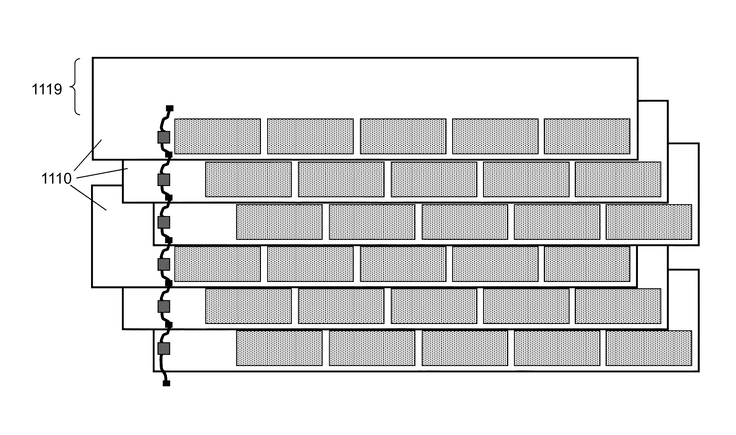
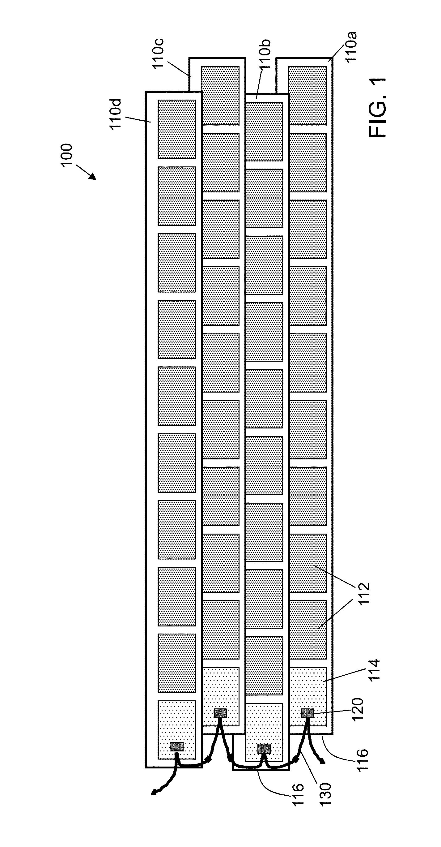
[0082]When identical strip-shaped photovoltaic modules are installed on a roof in an array, electrical interconnections between modules are made to build voltage in the array and to provide a route for the generated electrical power to be removed from the roof to a larger electrical system. To avoid penetrations through the roof, electrical elements such as junction boxes and wiring components can be provided near an end of each module. When modules have photovoltaic elements or other features arranged to emulate a shingle-like or tile-like effect,...


PUM


Abstract

The present invention relates generally to the photovoltaic generation of electrical energy. The present invention relates more particularly to photovoltaic arrays for use in photovoltaically generating electrical energy. One aspect of the invention is a photovoltaic array including a first photovoltaic module and a second photovoltaic module, each comprising a set of linearly arranged features extending from its lateral edge, and an electrical element on its surface, wherein the lateral distance between the electrical element and the center of the linearly-arranged feature closest to the lateral edge is different in the first photovoltaic module than in the second.

Description

CROSS-REFERENCE TO RELATED APPLICATIONS[0001]This application is a divisional of U.S. patent application Ser. No. 12 / 946,452, filed Nov. 15, 2010, which claims priority under 35 U.S.C. §119(e) to U.S. Provisional Patent Application Ser. No. 61 / 261,638, filed Nov. 16, 2009, each of which is hereby incorporated herein by reference in its entirety.BACKGROUND OF THE INVENTION[0002]1. Field of the Invention[0003]The present invention relates generally to the photovoltaic generation of electrical energy. The present invention relates more particularly to photovoltaic roofing products for use in photovoltaically generating electrical energy.[0004]2. Technical Background[0005]The search for alternative sources of energy has been motivated by at least two factors. First, fossil fuels have become increasingly expensive due to increasing scarcity and unrest in areas rich in petroleum deposits. Second, there exists overwhelming concern about the effects of the combustion of fossil fuels on the ...

Claims


Application Information

Patent Timeline
Patent Type & Authority Applications(United States)
IPC IPC(8): H01L31/05H01L31/048
CPCH02S20/23H02S40/34H01L31/0482H01L31/05H01L31/0504H01L31/0485Y02E10/50H02S40/36Y02B10/12Y02B10/10
Inventor KALKANOGLU, HUSNU M.QUARANTA, JOSEPH J.KOCH, STEPHEN A.
Owner CERTAINTEED CORP
Why Eureka
Try Eureka