Antenna assembly and a plasma processing chamber having the same

a plasma processing chamber and anantenna technology, applied in the direction of plasma technique, electrical equipment, electric discharge tubes, etc., can solve the problems of crack formation, dielectric window breakage, disuniform temperature drop, etc., to improve maintenance and increase substrate treatment efficiency

Inactive Publication Date: 2014-03-27
GENERAL CO LTD
View PDF17 Cites 15 Cited by
  • Summary
  • Abstract
  • Description
  • Claims
  • Application Information

AI Technical Summary

Benefits of technology

[0021]An antenna assembly and a plasma processing chamber including the same according to the present invention can maintain the constant temperature of a dielectric window through the inductive antenna, the heat conductive member, and the heating plate to which cooling water is supplied during the repetitive substrate treatment process and substrate replacement process and thereby increase the substrate treatment efficiencies. Further, the plasma processing chamber can support the dielectric window more effectively and more strongly through the tilted support surface of the side ring, and can improve the maintenance by allowing the gas manifold and the top nozzle to have screw coupling configurations in between the metal ring gaskets.

Problems solved by technology

However, when local heat is generated during heating of the dielectric window, cracks may be formed due to disuniform temperature differences, and the dielectric window may be broken due to in-out pressure differences.
In this case, disuniform temperature drops are also problematic.
In its subsequent process, they may act as particles, and therefore may deteriorate substrate treatment efficiencies.

Method used


Image

  • Antenna assembly and a plasma processing chamber having the same
  • Antenna assembly and a plasma processing chamber having the same
  • Antenna assembly and a plasma processing chamber having the same

Examples


Embodiment Construction

[0026]The present invention now will be described more fully hereinafter with reference to the accompanying drawings, in which some, but not all, embodiments of the invention are shown. Indeed, this invention may be embodied in many different forms and should not be construed as limited to the embodiments set forth herein; rather, these embodiments are provided so that this disclosure will satisfy applicable legal requirements. Like numbers refer to like elements throughout.

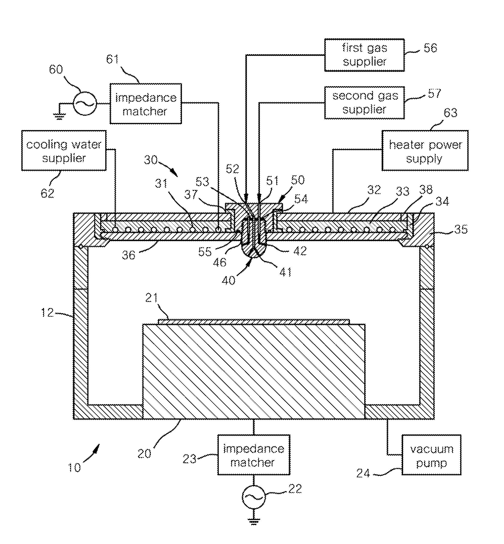
[0027]FIG. 1 is a sectional view of a plasma processing chamber according to one preferred embodiment of the present invention.

[0028]Referring to FIG. 1, the plasma processing chamber 10 according to a preferred embodiment of the present invention comprises a chamber body 12 and an antenna assembly 30 arranged thereon. The chamber body 12 has a substrate support 20 on which a substrate 21 to be processed is placed. In a ceiling part of the chamber body 12 in upper part of the substrate support 20, a dielectric wi...


PUM

PropertyMeasurementUnit
electromotive forceaaaaaaaaaa
heataaaaaaaaaa
heat conductiveaaaaaaaaaa

Abstract

A plasma processing chamber includes a chamber body having a substrate support on which the substrate to be processed is placed, a dielectric window forming a ceiling of the chamber body, an inductive antenna set on a upper part of the dielectric window and configured to supply an electromotive force generating plasmas into the chamber body, a cooling water supplier configured to supply cooling water into the inductive antenna, a heating plate set on a upper part of the inductive antenna, and a heat conductive member filled in a space between the heating plate and the dielectric window to contact the heating plate, the inductive antenna and the dielectric window, wherein the heat conductive member makes the dielectric window to have a uniform heat distribution through the heat conduction between the inductive antenna and the dielectric window, and the heat conduction between the heating plate and the dielectric window.

Description

CROSS-REFERENCE TO RELATED APPLICATION[0001]This application claims priority of Korean patent application numbers 10-2012-0106822 filed on Sep. 25, 2012. The disclosure of each of the foregoing applications is incorporated herein by reference in its entirety.FIELD OF THE INVENTION[0002]The present invention relates to a plasma processing chamber, and more particularly, to a plasma processing chamber equipped with an antenna assembly comprising a heating plate and a heat conductive member for constant temperature control.BACKGROUND OF THE INVENTION[0003]Plasma is a highly ionized gas containing an approximately equal number of positive ions and electrons. Plasma discharge is used for gas excitation to generate an active gas comprising ions, free radicals and molecules. An active gas is widely used in various fields. An active gas is generally used in semiconductor fabrication processes, for example, such as etching, deposition, cleaning, asking and the like.[0004]Types of plasma sour...

Claims


Application Information

Patent Timeline
Patent Type & Authority Applications(United States)
IPC IPC(8): H01J37/32
CPCH01J37/3211H01J37/32119H01J37/32522H01J37/3244
Inventor KIM, GYOO-DONGKANG, SUNG-YONG
Owner GENERAL CO LTD
Why Eureka
Try Eureka