Brake system

a brake system and pressure pulsation technology, applied in the direction of brake systems, valve operating means/release devices, transportation and packaging, etc., can solve the problems of limited reduction of pressure pulsation completely, increased manufacturing costs, and possible operating noise in the brake system, so as to reduce the frequency of pressure pulsation

Active Publication Date: 2014-03-27
HL MANDO CORP
View PDF5 Cites 6 Cited by
  • Summary
  • Abstract
  • Description
  • Claims
  • Application Information

AI Technical Summary

Benefits of technology

[0009]Therefore, it is an aspect of the present invention to provide a brake system capable of reducing periodic pressure pulsation generated by operation of a pump.

Problems solved by technology

However, since this is achieved by a structure that adjusts a cross-sectional area of a flow channel simply in order to reduce damping, there may be a limit in completely reducing pressure pulsation.
This method increases the overall performance of a motor and the weight and volume of a module, leading to an increase in manufacturing costs.
If a peak of pressure pulsation caused by driving of the pump is successively generated, operating noise in a brake system may occur.

Method used


Image

  • Brake system
  • Brake system
  • Brake system

Examples


Embodiment Construction

[0022]Reference will now be made in detail to the embodiments of the present invention, examples of which are illustrated in the accompanying drawings, wherein like reference numerals refer to like elements throughout.

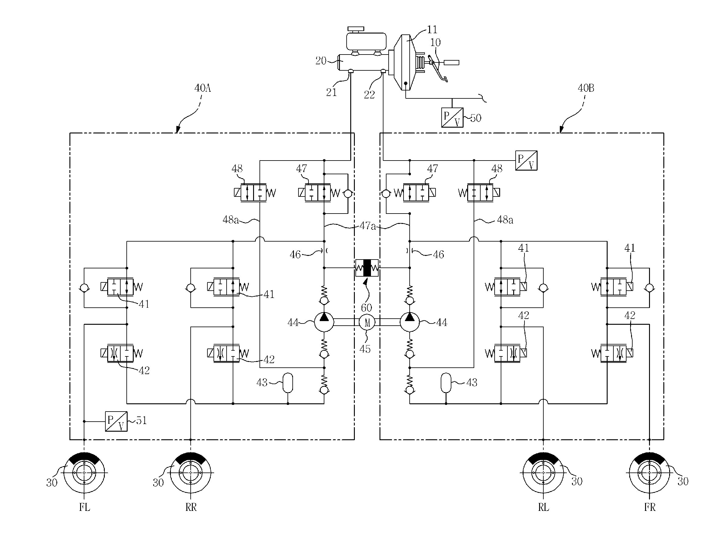
[0023]As shown in FIG. 1, a brake system according to an embodiment of the present invention includes a brake pedal 10 to receive a drivers manipulation force, a brake booster 11 to increase foot force using a pressure difference between vacuum pressure and atmospheric pressure caused by the foot force on the brake pedal 10, a master cylinder 20 to generate pressure through the brake booster 11, a first hydraulic circuit 40A to control transmission of oil pressure by connecting a first port 21 of the master cylinder 20 and two wheel brakes 30 (or wheel cylinders), and a second hydraulic circuit 40B to control transmission of oil pressure by connecting a second port 22 of the master cylinder 20 and the remaining two wheel brakes 30. The first hydraulic circuit 40A and t...


PUM


Abstract

Disclosed herein is a brake system capable of reducing periodic pressure pulsation generated by operation of a pump. The brake system includes a damper member provided with a cylinder having a step portion and a piston to reciprocate between the cylinder and the cap. The piston may be prevented from being excessively pushed toward one side of the damper member, and pressure pulsation generated by operation of the pump may be attenuated. Therefore, overall operating noise may be reduced during control the brake and product reliability may be increased.

Description

CROSS-REFERENCE TO RELATED APPLICATION(S)[0001]This application claims the benefit of Korean Patent Application No. 2012-0107538, filed on Sep. 27, 2012 in the Korean Intellectual Property Office, the disclosure of which is incorporated herein by reference.BACKGROUND[0002]1. Field[0003]Embodiments of the present invention relate to a brake system which may reduce pressure fluctuation which occurs during operation of a piston.[0004]2. Description of the Related Art[0005]A brake system is essentially mounted on a vehicle for braking of the vehicle, and various systems have recently been proposed to obtain stronger and more stable braking force. Examples of the brake system include an anti-lock braking system (ABS), a brake traction control system (BTCS), and a vehicle dynamic control system (VDC). The ABS prevents wheels from skidding upon braking. The BTCS prevents slippage of driving wheels during rapid acceleration from a stop or sudden unintended acceleration of a vehicle. The VDC...

Claims


Application Information

Patent Timeline
Patent Type & Authority Applications(United States)
IPC IPC(8): B60T13/14
CPCB60T13/142B60T8/4068B60T8/4872B60T8/36B60T11/16F16K31/06
Inventor LEE, CHUNG JAE
Owner HL MANDO CORP
Why Eureka
Try Eureka