
Lighting devices

a technology of light emitting diodes and light fixtures, which is applied in the direction of semiconductor devices for light sources, lighting and heating equipment with built-in power, etc., can solve the problems of premature lamp failure, potential fire hazards, and limited useful life of fluorescent tube lamps, so as to save energy and prolong the life , the effect of equal light distribution

Active Publication Date: 2014-03-27
APOGEE LIGHTING HLDG LLC
View PDF5 Cites 23 Cited by
  • Summary
  • Abstract
  • Description
  • Claims
  • Application Information

AI Technical Summary

Benefits of technology

The patent text describes replacing fluorescent tube based fixtures with linear LED light fixtures that provide same or better light output, distribution, and lifetime. Essentially, the lighting devices provide energy-efficient options for replacing traditional fixtures.

Problems solved by technology

Typical useful life of fluorescent tube lamps is limited to 15,000 hours.
Poor connections at the junction point of the lamp and socket results in premature lamp failure as well as a potential fire hazard due to arcing.
Older magnetic ballasts contain hazardous PCBs and pose a disposal problem when replaced with newer solid state ballasts.
Common fluorescent light fixtures are not dimmable and perform poorly in cold temperature applications when not jacketed.
Battery backed up fluorescent emergency lighting is complex (e.g., inverter type ballasts are required), is costly and provides a very limited operating time due to the high wattage needed.
LED tubes do not accept the voltage output of the existing fluorescent ballast.
Due to limitations in their construction LED tubes have a limited light projection angle which under-utilizes the existing reflector and creates a narrower and distorted light distribution profile with shadows and hot spots.
The limited heat dissipation of the tube heat sink typically shortens the product life of the LEDs and the encapsulated driver electronics.
The wattage of the LED tube is practically limited by the ability to dissipate heat from the encapsulated light engine.
The constant current / voltage integral driver encapsulated within the LED tube does not provide any means for dimming the light output.
Emergency battery backup operation is once again complex, costly and provides a very limited operating time due to the high wattage of the entire tube system.

Method used


Image

  • Lighting devices
  • Lighting devices
  • Lighting devices

Examples


Embodiment Construction

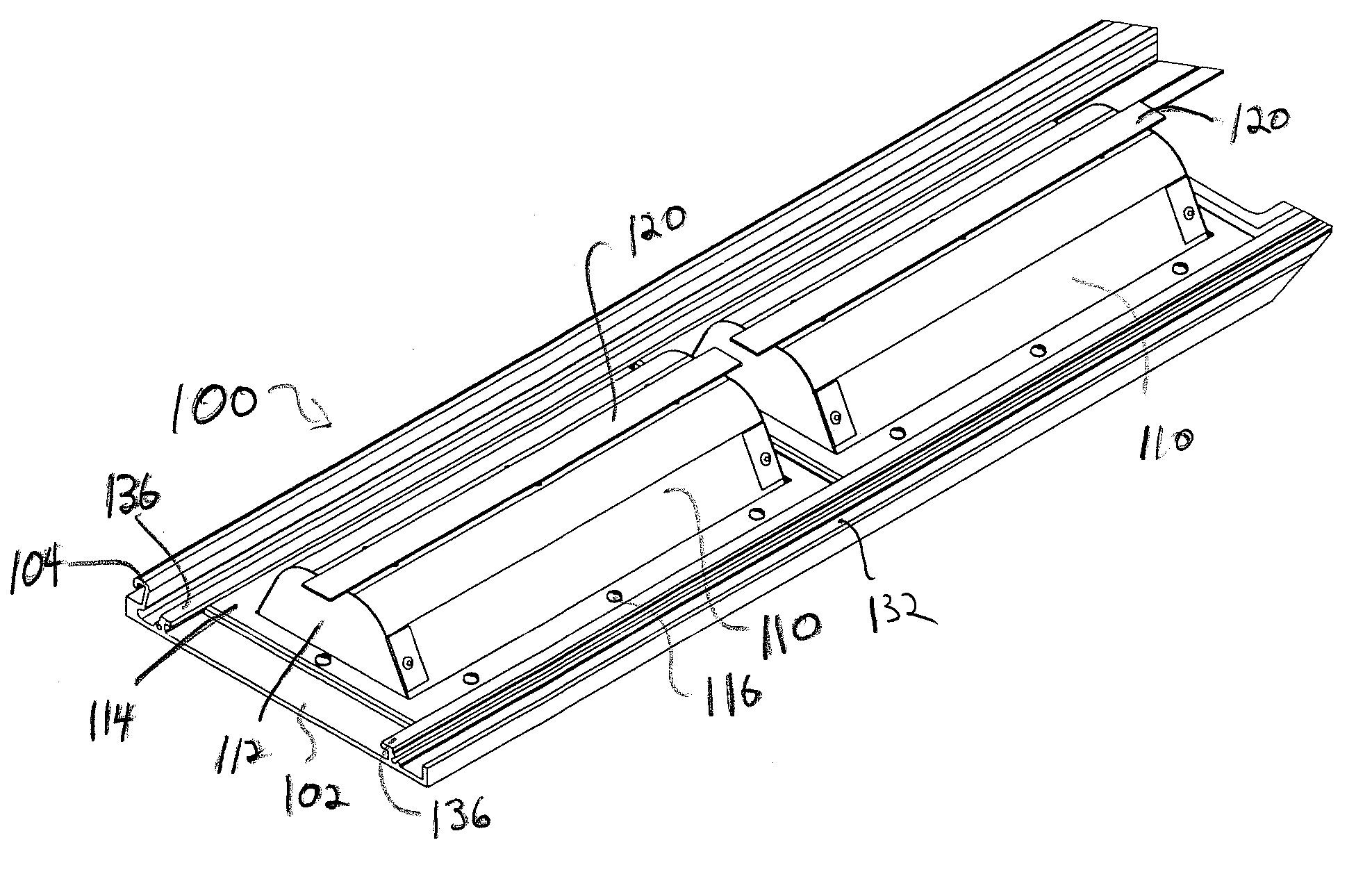
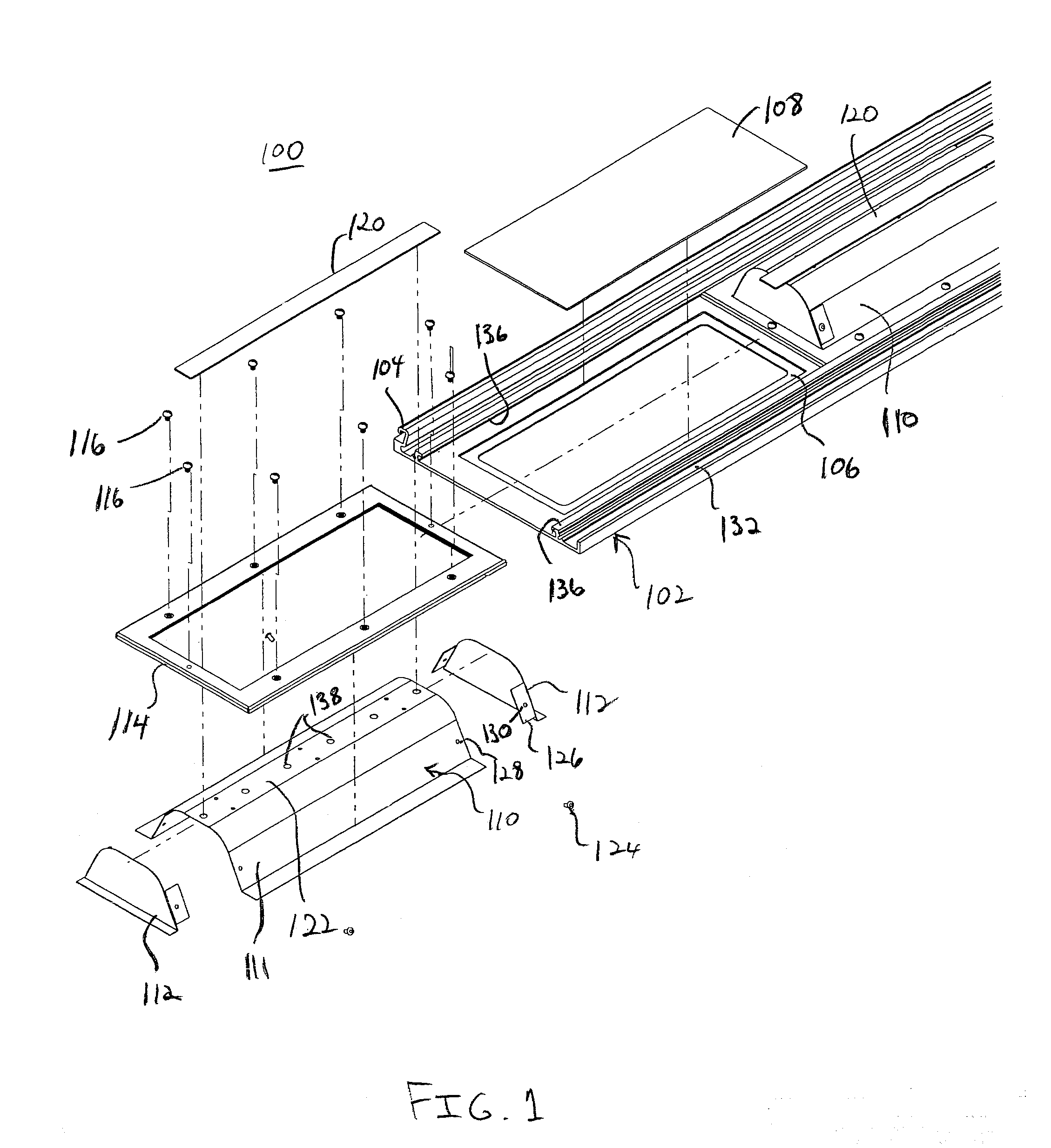
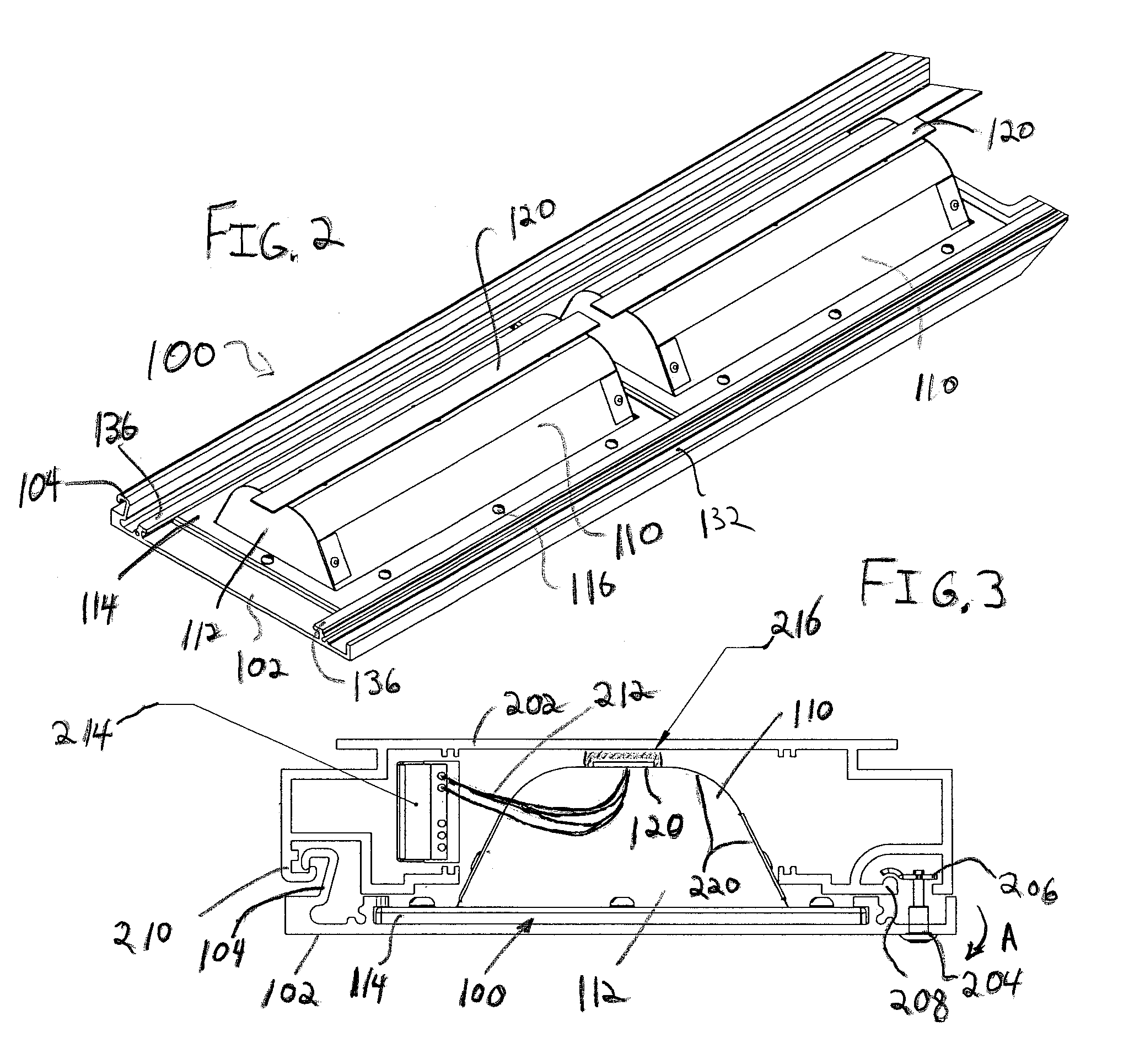
[0028]In accordance with the present principles, light fixtures are provided that overcome the deficiencies of the prior art. In one embodiment, a light emitting diode (LED) array is provided that can be retrofitted in an existing fluorescent lamp housing and can be wired directly to power leads or around existing ballast or sockets as needed. In another embodiment, the LED array is employed in a custom designed lamp. A linear non-tube LED based light fixture can replace or retrofit existing light fixtures and provide equal or better light performance, extended service life, greater reliability, significant energy savings and enhanced operating features (e.g., dimming, instant start, battery backup operation, etc.).

[0029]It is to be understood that the present invention will be described in terms of a given illustrative structure or architecture having illustrative circuit layouts; however, other architectures, structures, components and process features and steps may be varied with...


PUM

PropertyMeasurementUnit
Electrical conductoraaaaaaaaaa

Abstract

A lighting device includes a cover portion configured to have a hinged connection for mounting on a housing. The cover portion includes a light emitting diode (LED) and a mixing chamber having a reflective internal surface for receiving light from the LED. A phosphorescent lens is disposed opposite the LED and is configured to reflect light from the LED back to the mixing chamber and to emanate absorbed light from the lens to a surrounding region outside of the mixing chamber. An LED driver circuit is configured to power the LED, the LED driver circuit being electrically connected to a power source. Other embodiments are also disclosed.

Description

BACKGROUND[0001]1. Technical Field[0002]The present invention relates to light fixtures, and more particularly to light emitting diode fixtures configured for easy maintenance and efficient use for retrofit in or replacement of fluorescent lights or fixtures.[0003]2. Description of the Related Art[0004]Existing linear fluorescent lighting fixtures utilize tube lamping in conjunction with a ballast and reflector to provide a lighting solution. Omnidirectional light output from a linear fluorescent light source is either directly or indirectly projected from the fixture in conjunction with some form of reflecting system or lens. Typical fluorescent tubes are terminated with either a single pin or multiple pins which are fit into sockets which are wired to a ballast.[0005]Typical useful life of fluorescent tube lamps is limited to 15,000 hours. Poor connections at the junction point of the lamp and socket results in premature lamp failure as well as a potential fire hazard due to arcin...

Claims


Application Information

Patent Timeline
IPC IPC(8): F21V13/04F21V29/00B23P17/04F21V9/16
CPCF21S9/022F21V5/10F21V7/0008F21V7/005F21V9/40F21V13/14F21V29/777F21Y2103/10F21Y2115/10Y10T29/49716F21V13/04
Inventor NICOLAI, RICHARDGAON, MARTIN
Owner APOGEE LIGHTING HLDG LLC
Learn More