Transmission apparatus and processing method thereof

a technology of transmission apparatus and processing method, which is applied in the field of transmission apparatus, can solve problems such as optical fiber breaking off, and achieve the effect of high-reliability transmission

Inactive Publication Date: 2014-03-27
NEC CORP
View PDF1 Cites 0 Cited by
  • Summary
  • Abstract
  • Description
  • Claims
  • Application Information

AI Technical Summary

Benefits of technology

[0024]In accordance with the present invention, for a transmission apparatus in which a communication unit that converts an SDH / PDH signal to a packet signal by means of a Pseudo-Wire technique is inserted into a slot of the apparatus so that the control board only possesses a packet switch, it is possible for the transmission apparatus to convert a signal for the SDH / PDH signal into a radio signal or an optical transmission signal and to output the converted signal to an appropriate device.
[0025]Additionally, in accordance with the present invention, a redundant arrangement is applied to each input signal so that the output route can be appropriately chosen between one that utilizes a radio signal and one that utilizes an optical transmission signal. Therefore, a highly reliable transfer can be performed in the relevant communication even when a change in the environment or a serious disaster occurs.
[0026]That is, if the frequency band for radio transmission should be restricted due to environmental degradation, such restriction can be compensated utilizing optical transmission. On the other hand, if an optical fiber is broken off due to a serious disaster or the like, the relevant transmission path can be secured utilizing radio transmission.

Problems solved by technology

On the other hand, since optical transmission utilizes an optical fiber as a transmission medium, it has a risk such that the optical fiber may be broken off due to an earthquake, a fire, road work, or the like.

Method used


Image

  • Transmission apparatus and processing method thereof
  • Transmission apparatus and processing method thereof
  • Transmission apparatus and processing method thereof

Examples


Embodiment Construction

[0034]Below, an embodiment of the present invention will be explained in detail with reference to the drawings.

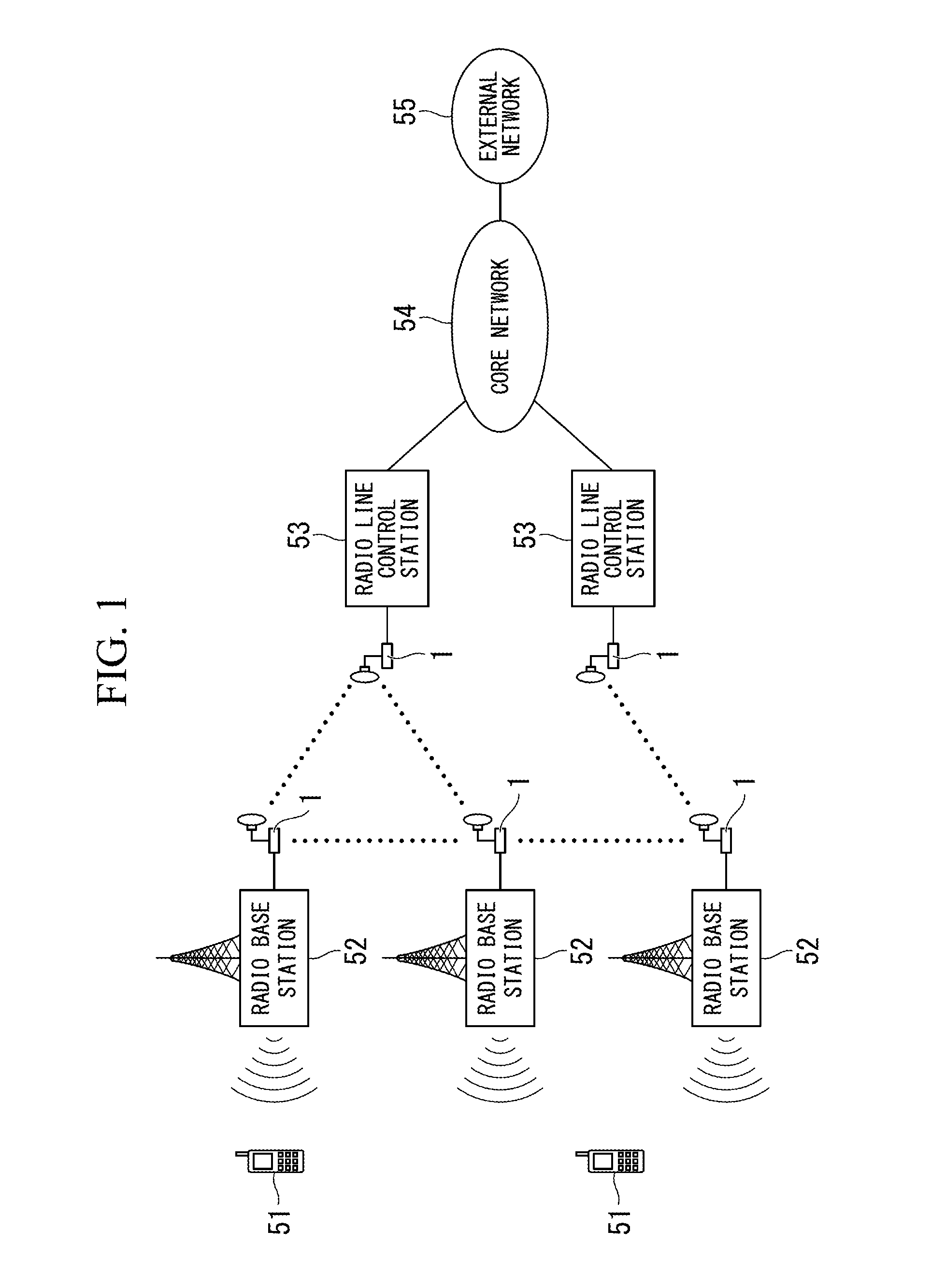
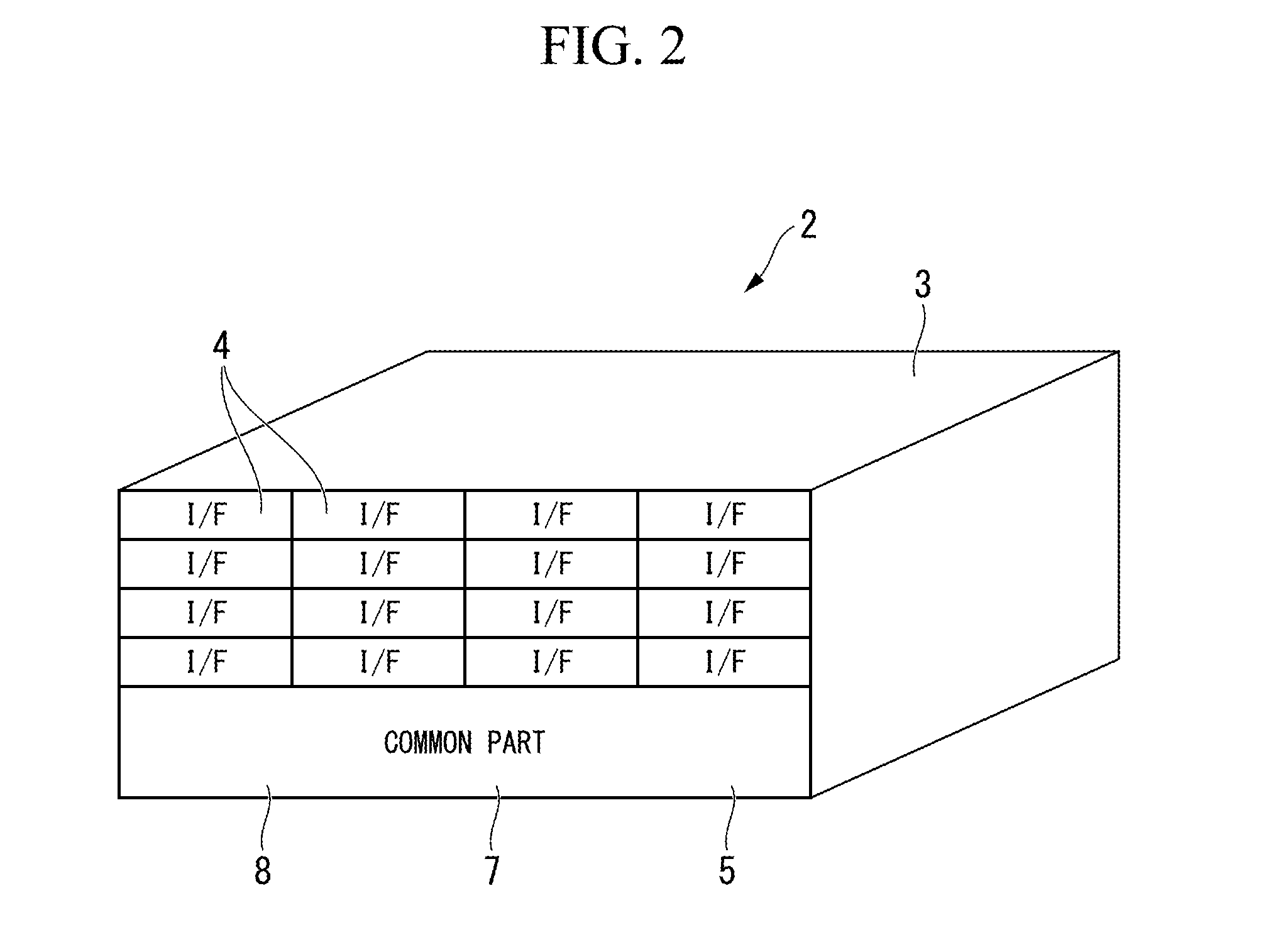
[0035]FIG. 1 is a diagram showing the structure of a communication network 50 to which a transmission apparatus 2 (see FIG. 2) in accordance with the present embodiment is applied.

[0036]The communication network 50 has radio terminals 51 such as cellular phones, radio base stations 52, radio line control stations 53, a core network 54, and an external network 55.

[0037]Each radio terminal 51 can perform communication within a range which can receive radio waves from any radio base station 52.

[0038]Each radio base station 52 is connected to a radio line control station 53 as an upper station, and the radio line control station 53 controls a plurality of the radio base stations 52.

[0039]In addition, each radio line control station 53 is connected to the core network 54.

[0040]The core network 54 is connected to the external network 55 (e.g., a mobile communication network opera...


PUM


Abstract

A transmission apparatus includes a package that has a plurality of slots into each of which a board can be freely detachably inserted; at least one control board; a PWE interface communication unit that is connected to the control board, converts an input SDH or PDH signal to a packet signal, and outputs the converted signal to the control board; a radio transmission communication unit that is connected to the control board, converts the packet signal to a radio signal, and outputs the converted signal; and an optical transmission communication unit that is connected to the control board, converts the packet signal to an optical transmission signal, and outputs the converted signal. The units are separately inserted in the slots.

Description

TECHNICAL FIELD[0001]The present invention relates to a transmission apparatus that relays a communication signal, and a processing method thereof[0002]Priority is claimed on Japanese Patent Application No. 2011-113222, filed May 20, 2011, the contents of which are incorporated herein by reference.BACKGROUND ART[0003]Regarding characteristics of radio transmission that utilizes spatial propagation, transmission performance may vary due to environmental conditions about weather, obstruction, or the like. Therefore, when the weather condition is bad, the radio transmission should be operated within a restricted frequency band.[0004]On the other hand, since optical transmission utilizes an optical fiber as a transmission medium, it has a risk such that the optical fiber may be broken off due to an earthquake, a fire, road work, or the like. Therefore, if an optical fiber for optical transmission is broken off due to an earthquake or the like, a detour should be established so as not to...

Claims


Application Information

Patent Timeline
Patent Type & Authority Applications(United States)
IPC IPC(8): H04B10/03
CPCH04B10/03H04B1/74H04B10/801H04J3/1611H04J3/1623H04J2203/0026H04Q2213/13098H04L12/6418H04Q11/04
Inventor OKUYAMA, KEIICHI
Owner NEC CORP
Why Eureka
Try Eureka