Cleanroom and Cleaning Apparatus

a cleaning apparatus and vacuum technology, applied in lighting and heating apparatus, heating types, separation processes, etc., can solve the problems of permanent damage to ic and ito, difficult to remove dust clusters, etc., and achieve excellent performance, reduce static electricity, and increase product yield

Inactive Publication Date: 2014-03-27
TCL CHINA STAR OPTOELECTRONICS TECH CO LTD
View PDF23 Cites 3 Cited by
  • Summary
  • Abstract
  • Description
  • Claims
  • Application Information

AI Technical Summary

Benefits of technology

[0005]It is an object of the present invention to provide a cleanroom and a cleaning apparatus incorporated therewith so as to effectively eliminate the static electricity generated within the cleanroom.
[0008]A cleaning unit is arranged on a ceiling of the cleanroom and which provides a cleaned, ionized air flow so as to eliminate a static electricity and airborne particles accumulated over a surface of a glass substrate.
[0012]A cleaning unit is arranged on a ceiling of the cleanroom and which provides a cleaned, ionized air flow so as to eliminate a static electricity and airborne particles accumulated over a surface of a glass substrate.
[0019]According to a preferred embodiment, wherein the cleanroom includes a blower disposed on the bottom floor of the cleanroom, a vertex within the cleanroom can be readily reduced by creating a vertical airflow between the cleaning unit and the blower.
[0023]In order to resolve the issues encountered by the prior art, the present invention provides a technical solution by introducing a cleaning apparatus includes a cleaning unit providing a cleaned, ionized air flow so as to eliminate a static electricity and airborne particles accumulated over a surface of a glass substrate. The cleaning unit includes a blower, a filtering device, and negative ion purifier so as to provide ionized airflow after the air is drawn in through the blower, filtered with the filtering device, and eventually ionized by the negative ion cleaner.
[0024]The present invention can be concluded with the following advantages. As compared to the existing prior art, the cleanroom made in accordance with the present invention provides a measurement to eliminate the static electricity. An ionized airflow is generated so as to remove the airborne particles and static electricity accumulated over the glass substrate. It features an excellent performance, and therefore increases the yield of the product.

Problems solved by technology

However, static electricity can readily be generated resulted from all kinds of frictions, conductance etc, and the airborne dust and particles can readily stick to certain surface because of the static electricity and because of that, the dust cluster is very difficult to remove.
In addition, the static electricity can also cause a permanent damage to IC and ITO as it can create an electrical shock penetrating those elements.

Method used


Image

  • Cleanroom and Cleaning Apparatus
  • Cleanroom and Cleaning Apparatus
  • Cleanroom and Cleaning Apparatus

Examples


Embodiment Construction

[0031]In order clearly explain the technology of the embodiment illustrated in the present invention, a brief and concise description will be given along with the accompanied drawings. Apparently, the embodiments illustrated in the drawings are merely some typical embodiments and which can be readily modified by the skilled in the art without any additional laborious efforts so as to transform them into other drawings, and they should all be covered by the appended claims.

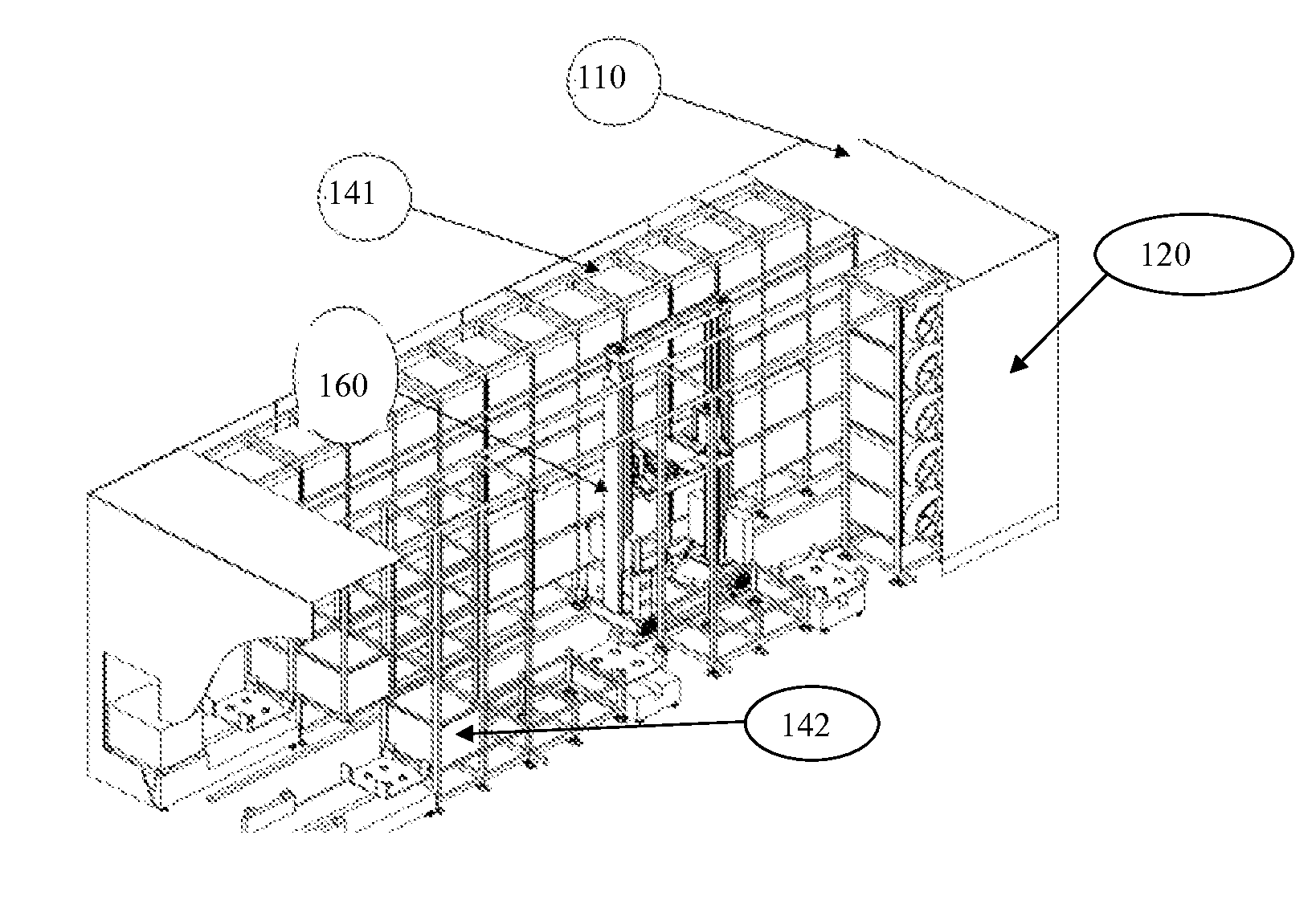
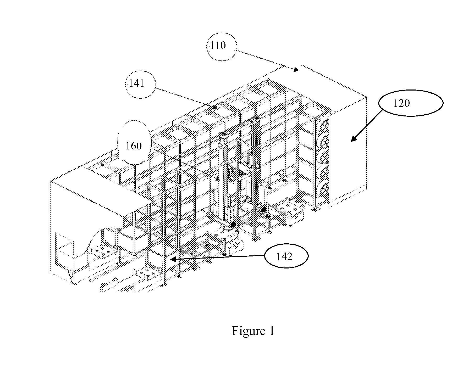
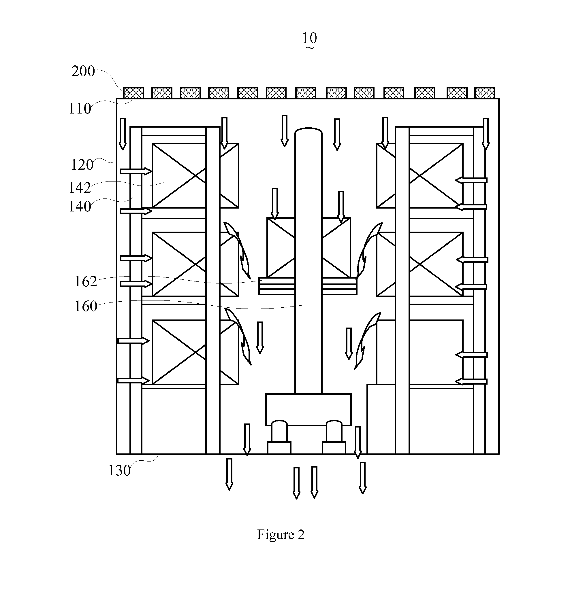
[0032]Referring to FIGS. 1 to 3, a cleanroom 10 is provided for storing glass substrates. The cleanroom 10 includes an outlet 102 and a cleaning unit 200.

[0033]The outlet 102 is arranged on a bottom floor of the cleanroom 10, and the cleaning unit 200 is arranged on a top ceiling of the cleanroom 10. The cleaning unit 200 supplies a cleaned, ionized airflow to the cleanroom 10 so as to remove airborne particles within the cleanroom 10 and dust, particles accumulated over a surface of the glass substrate.

[0034]Subst...


PUM

PropertyMeasurementUnit
particle sizeaaaaaaaaaa
temperatureaaaaaaaaaa
humidityaaaaaaaaaa

Abstract

The present invention discloses a cleanroom for storing glass substrates. The cleanroom includes an outlet disposed on a bottom of the cleanroom. A cleaning unit is arranged on a ceiling of the cleanroom and which provides a cleaned, ionized air flow so as to eliminate a static electricity and airborne particles accumulated over a surface of a glass substrate. In addition, the present invention further provides a cleaning unit. An ionized airflow is generated so as to remove the airborne particles and static electricity accumulated over the glass substrate. It features an excellent performance, and therefore increases the yield of the product.

Description

FIELD OF THE INVENTION[0001]The present invention relates to a technology of manufacturing of liquid crystal display device, and more particularly, to a cleanroom and a cleaning apparatus incorporated to the cleanroom.DESCRIPTION OF PRIOR ART[0002]Cleanroom is also referred to as dust-free room remained with a low level of environmental pollutants, such as dust, airborne microbes, aerosol particles and chemical vapors. More accurately, a cleanroom has a controlled level of contamination that is specified by the number of particles per cubic meter at a specified particle size. In the field of manufacturing a high tech product, such as a glass substrate used to make liquid crystal display device, the cleanness, temperature and humidity of the environment have to be controlled to within a controlled range so as to ensure the glass substrate manufactured therefrom meet the preset requirements.[0003]In the existing cleanroom, an inlet with a filter is arranged on a ceiling of the cleanro...

Claims


Application Information

Patent Timeline
Patent Type & Authority Applications(United States)
IPC IPC(8): H05F1/00F24F3/16
CPCF24F3/161H05F1/00F24F3/167F24F8/30
Inventor JIANG, YUNSHAOWU, CHUNHAOLIN, KUNHSIENWANG, YONGQIANGSHU, ZHIYOUGUO, ZHENHUA
Owner TCL CHINA STAR OPTOELECTRONICS TECH CO LTD
Why Eureka
Try Eureka