Mechanical Chest Compression Plunger Adapter and Compression Pad

Active Publication Date: 2014-03-27
ZOLL MEDICAL CORPORATION
View PDF2 Cites 16 Cited by
  • Summary
  • Abstract
  • Description
  • Claims
  • Application Information

AI Technical Summary

Benefits of technology

The invention describes a device and method for compressing a patient's chest in a way that maintains the proper position on the patient's chest. The device includes a plunger adapter and a detachable compression pad that can be secured to the patient's sternum. The plunger adapter engages with the compression pad and applies compression to the patient's chest at a specific location. This allows for proper positioning of the compression force on the patient's chest during use. The compression pad is designed to adapt to the shape of the patient's chest and can be made of layers to optimize the application of compression. The device also includes magnets to create a retention force between the plunger and plunger adapter, providing some expansion force to the patient's chest between compressions. The technical effect of the invention is to provide a device that can compress a patient's chest at a specific location with optimal force and minimal risk of tearing the patient's skin or tissue.

Problems solved by technology

However, even experienced paramedics cannot maintain adequate chest compressions for more than a few minutes.
Thus, CPR is not often successful at sustaining or reviving the patient.
As mechanical compressions are performed by piston based chest compression systems, the compression pads may shift position relative to the patient and the effectiveness of the automated chest compressions are diminished.

Method used


Image

  • Mechanical Chest Compression Plunger Adapter and Compression Pad
  • Mechanical Chest Compression Plunger Adapter and Compression Pad
  • Mechanical Chest Compression Plunger Adapter and Compression Pad

Examples


Embodiment Construction

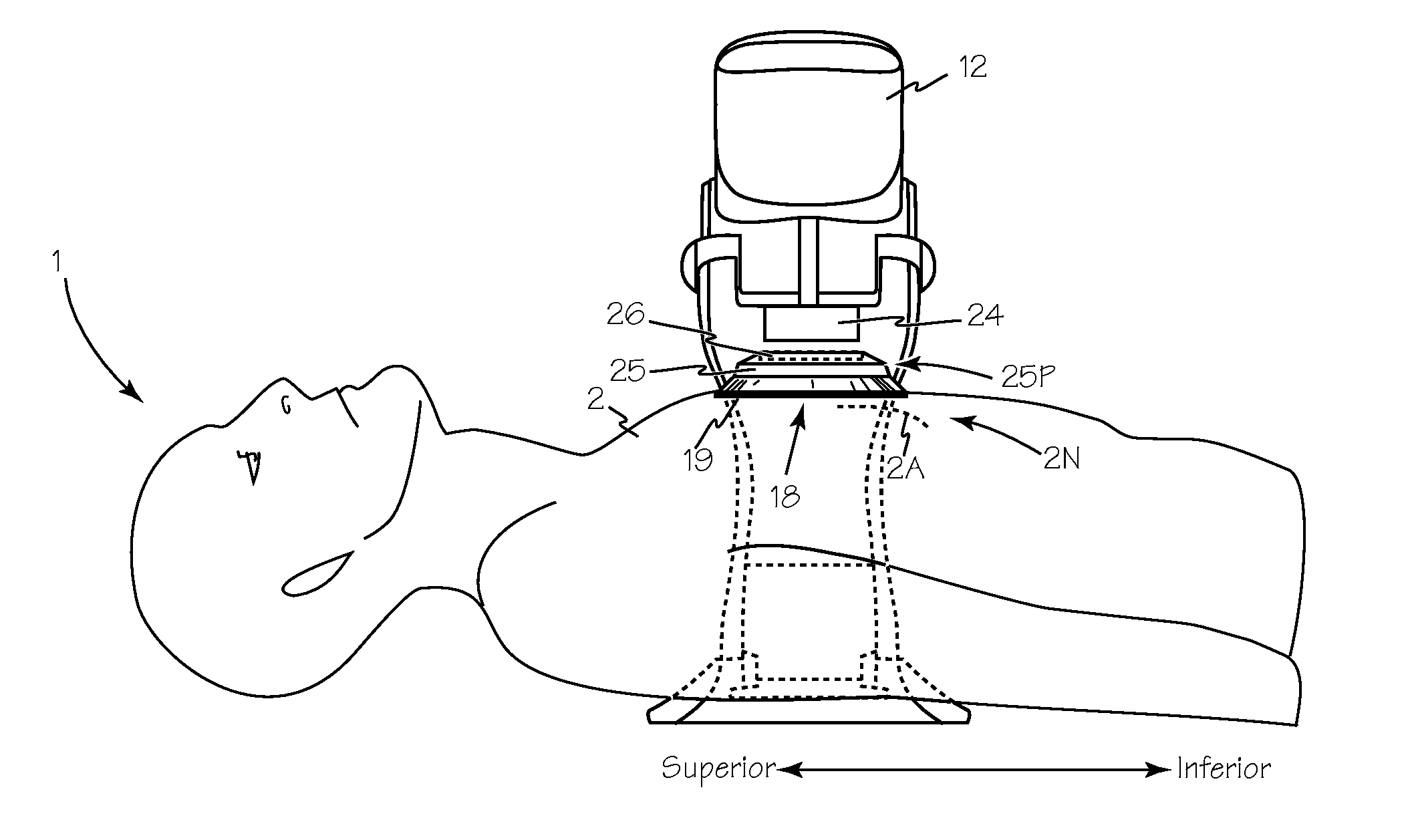
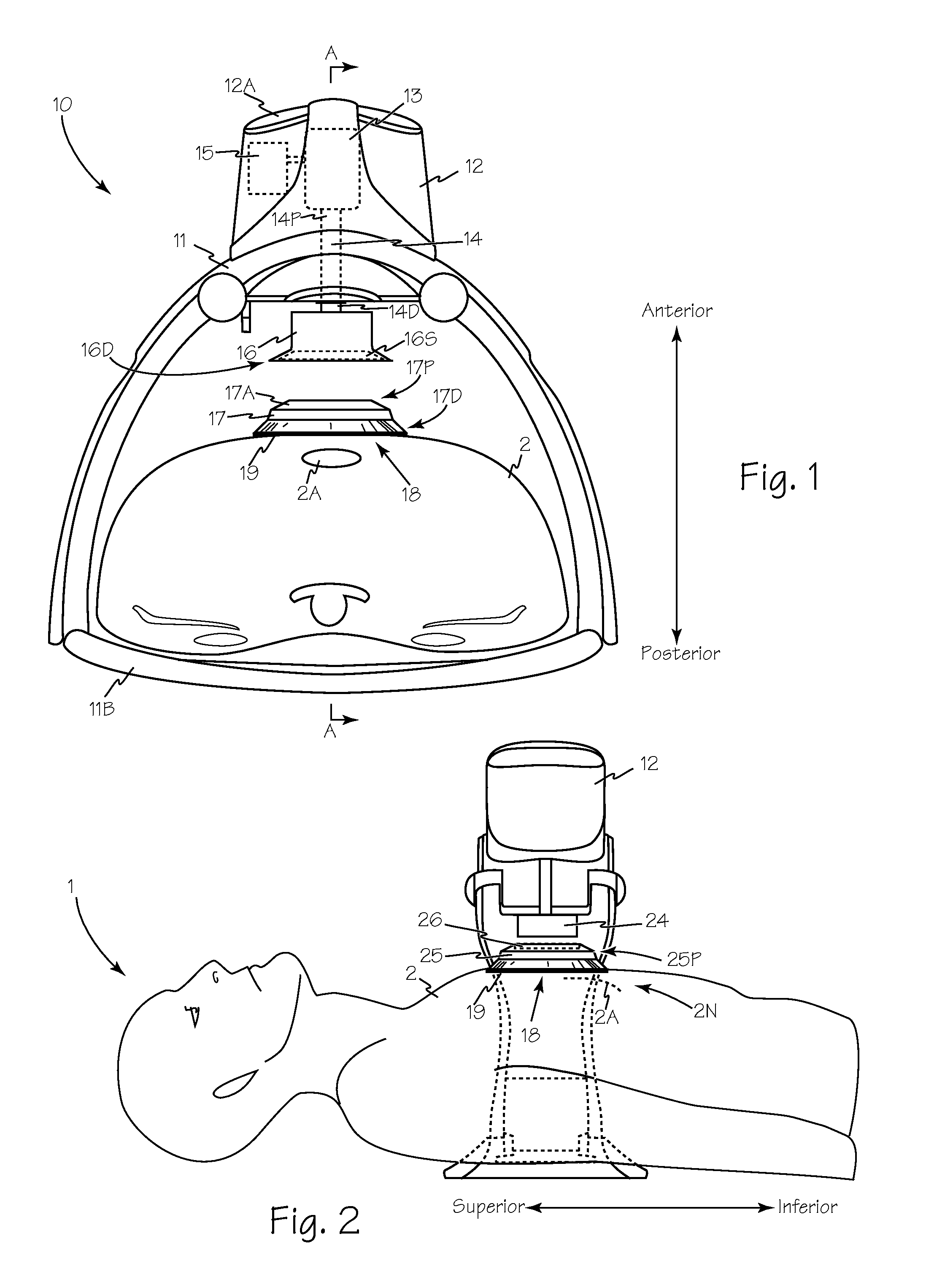
[0025]In FIG. 1, mechanical chest compression device 10 is oriented to apply compressions to the chest 2 of patient 1. Chest compression device 10 includes support structure 11 and backboard 11B which supports and orients chest compression unit 12 apposing sternum 2A. Chest compression unit 12 includes any suitable drive means such as motor 13 which may be a reversible electromotor, a linear actuator or the like. Plunger 14 has a distal end 14D and a proximal end 14P, and proximal end 14P of the plunger is operably coupled to motor 13. Distal end 14D of the plunger extends from and withdraws into the housing upon operation of motor 13. A motor control unit such as controller 15 is operably connected to motor 13 and includes a microprocessor to control the operation of the motor and the plunger. Plunger adapter 16 is secured to the distal end of the plunger and compression pad 17 removably engages the plunger adapter.

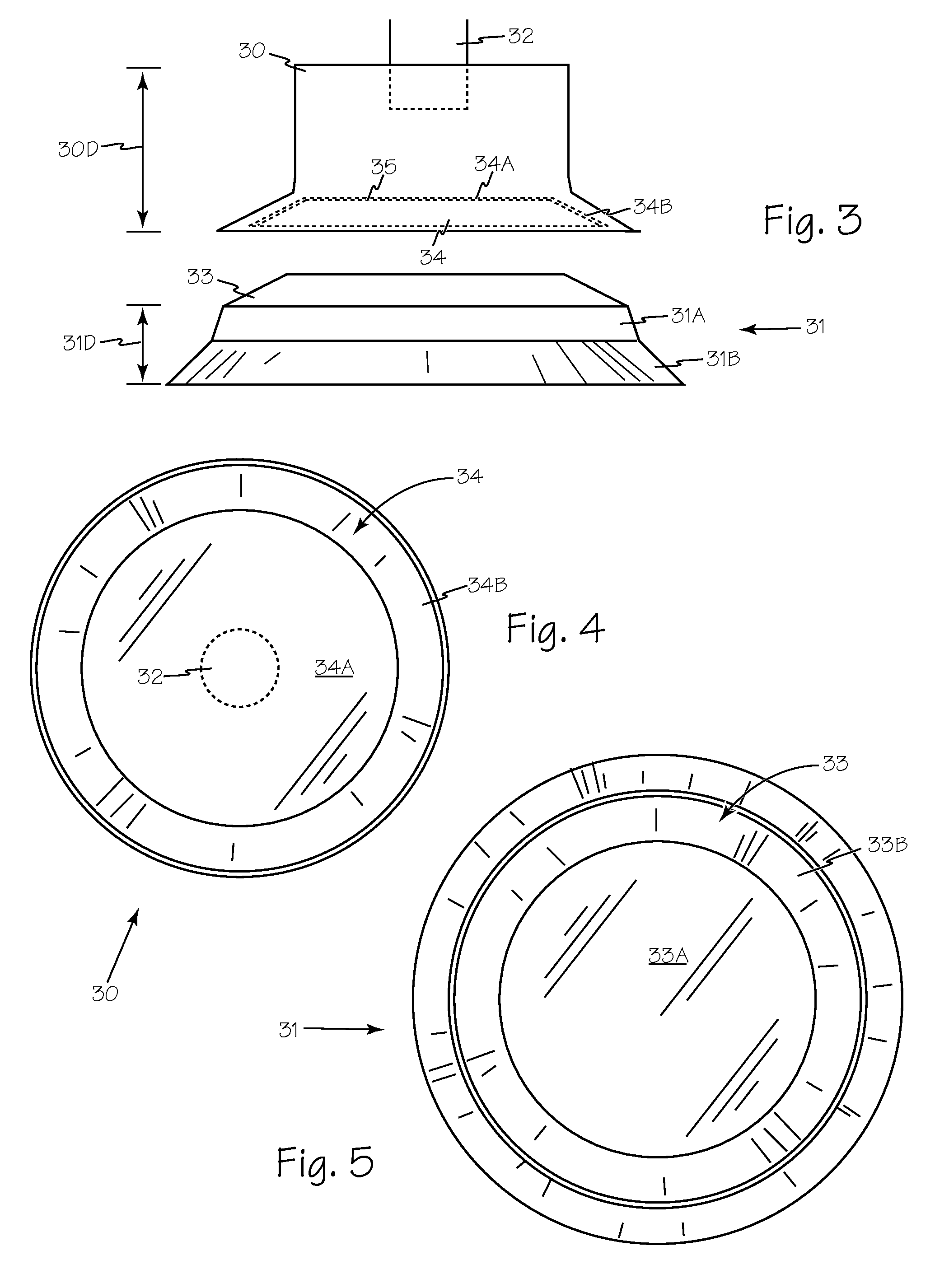
[0026]Distal end 16D of plunger adapter 16 is sized and shaped to a...


PUM


Abstract

A plunger adapter and a detachable compression pad for piston driven chest compression devices optimizes the application of chest compressions to a fixed location on a patient's chest. The detachable compression pad may be removably secured to the patient above the patient's sternum to ensure that the compression pressure from the piston through the piston adapter is applied to a fixed location on the patient's chest. As the plunger and plunger adapter retract from the chest, the compression pad remains fixed to the patient's chest, and as the plunger and plunger adapter extend from the chest compression unit for subsequent compression strokes, the distal end of the plunger adapter reengages the compression pad to apply compression to a fixed location on the patient's chest. Suitable engagement mechanisms may be included in the plunger adapter and compression pad to provide a preselected level of chest expansion force in addition to chest compression force.

Description

FIELD OF THE INVENTIONS[0001]The inventions described below relate to the field of emergency medical devices and methods and more specifically to methods and device to optimize the resuscitation of cardiac arrest patients.BACKGROUND OF THE INVENTIONS[0002]According to the American Heart Association nearly 383,000 out-of-hospital sudden cardiac arrests occur annually in the United States. These patients may be saved by the timely application of life saving measures such as Cardiopulmonary resuscitation (CPR).[0003]CPR is a well-known and valuable method of first aid used to resuscitate people who have suffered from cardiac arrest. CPR requires repetitive chest compressions to squeeze the heart and the thoracic cavity to pump blood through the body. Artificial respiration, such as mouth-to-mouth breathing or a bag mask device, is used to supply air to the lungs. When a first aid provider performs manual chest compression effectively, blood flow in the body is about 25% to 30% of norma...

Claims


Application Information

Patent Timeline
IPC IPC(8): A61H31/00
CPCA61H31/00A61H2201/1664A61H2201/1215A61H2201/1253A61H2201/149A61H31/006A61H2031/001
Inventor PARASCANDOLA, MICHAELFREEMAN, GARY
Owner ZOLL MEDICAL CORPORATION
Why Eureka
Try Eureka