Self-leveling welding tractor

a welding tractor and self-leveling technology, applied in non-electric welding apparatuses, welding/cutting auxillary devices, auxillary welding devices, etc., can solve problems such as unsatisfactory or incomplete welds, upset or unsteady rocking of welding tractor,

Inactive Publication Date: 2014-04-03
LINCOLN GLOBAL INC
View PDF3 Cites 25 Cited by
  • Summary
  • Abstract
  • Description
  • Claims
  • Application Information

AI Technical Summary

Benefits of technology

[0008]In another aspect, a level sensor communicates the position the welding tractor to a controller located remotely and communicating with the level sensor and the motor through either a cable or wireless protocol. The controller

Problems solved by technology

A change in rotation can cause the welding tractor to upset or unsteadily rock from its positi

Method used


Image

  • Self-leveling welding tractor
  • Self-leveling welding tractor
  • Self-leveling welding tractor

Examples


Embodiment Construction

[0018]Referring now to the figures, several embodiments or implementations of the present invention are hereinafter described in conjunction with the drawings, wherein like reference numerals are used to refer to like elements throughout. The present disclosure is related to a self-leveling welding tractor for welding about the circumference of a cylindrical object. Although illustrated and described hereinafter in the context of various exemplary welding products, methods, and systems, the invention is not limited to the illustrated examples.

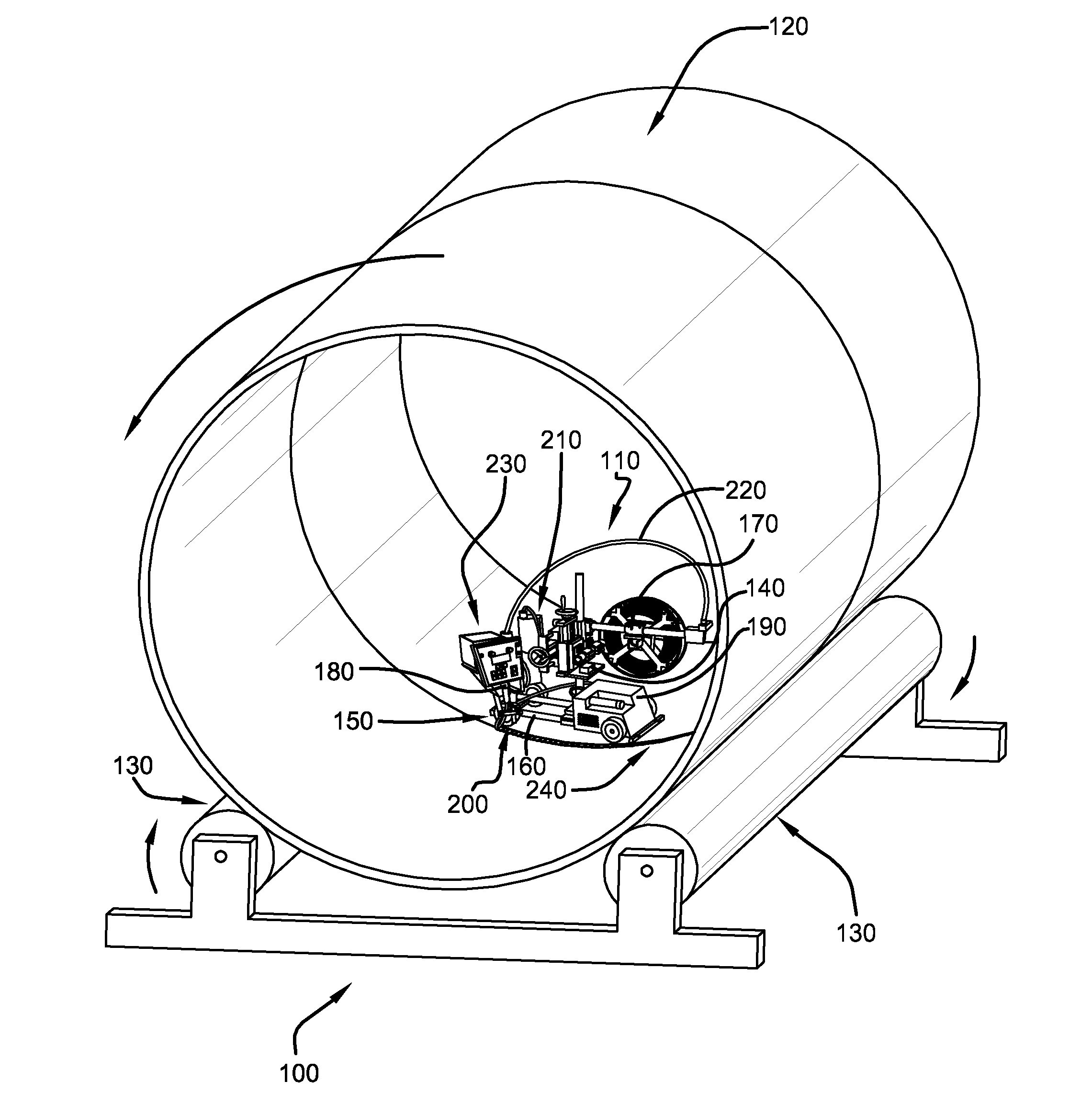
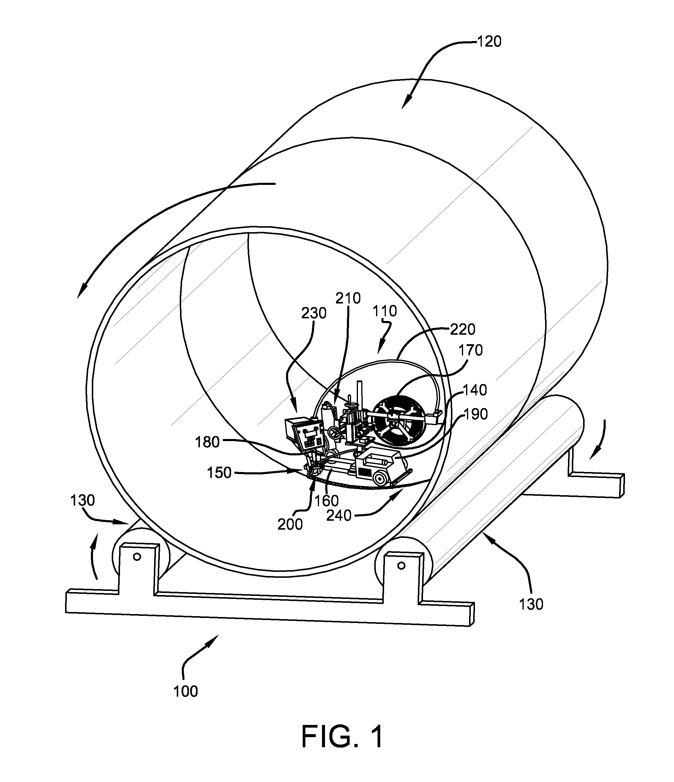
[0019]FIG. 1 illustrates welding system 100, which includes welding tractor 110 at least partially within at least one cylindrical object 120. Cylindrical object 120 is being supported and stabilized by at least two rollers 130. Welding tractor 110 is located in a forward moving position wherein welding tractor 110 remains stationary as cylindrical object 120 rotates about its longitudinal axis as welding system 100 is in rotational motion. Thu...


PUM

PropertyMeasurementUnit
Angleaaaaaaaaaa
Angleaaaaaaaaaa
Angleaaaaaaaaaa

Abstract

A welding tractor is described as well as a process for using the tractor in which a predefined angle of inclination or declination is maintained during a circumferential welding process.

Description

TECHNICAL FIELD[0001]The present disclosure is related to a welding system, and more particularly, to products, methods, and systems to remotely circumferentially weld cylindrical joints of objects during rotation.BACKGROUND OF INVENTION[0002]Cylindrical objects often require welds on their interior or exterior circumference. Such cylindrical objects, for example, include pipes, tanks, and the like. Welds are used, for example, to connect two cylindrical objects, seal a cylindrical object, repair a cylindrical object, apply cladding and the like. It is common that remote welding tractors are used within the confined interior space or upon exterior locations of a cylindrical object. To complete a weld, welding tractors travel about the circumference of the cylindrical object. To keep these tractors in contact with the surface of the cylindrical object, the cylindrical object is often rotated about its longitudinal axis. Therefore, the welding tractor maintains its original location i...

Claims


Application Information

Patent Timeline
IPC IPC(8): B23K3/00B23K31/02
CPCB23K9/0284B23K9/16B23K37/0276B23K37/0282B23K37/0294B23K2101/06B23K2101/10B23K2103/04
Inventor PETERS, STEVEN R.ENYEDY, EDWARD A.
Owner LINCOLN GLOBAL INC
Why Eureka
Try Eureka