Radome for a radar sensor assembly

a technology for radar sensors and radome, which is applied in the direction of wave based measurement systems, instruments, and reradiation, can solve the problems of not being convenient or feasible to provide a uniform radome, and achieve the effect of minimizing the distortion of the radar beam

Inactive Publication Date: 2014-04-03
DELPHI TECH INC
View PDF14 Cites 38 Cited by
  • Summary
  • Abstract
  • Description
  • Claims
  • Application Information

AI Technical Summary

Benefits of technology

[0003]Described herein is a radome includes aesthetic features on the exposed...

Problems solved by technology

However, when a radar sensor is adapted for use on a vehicle, it may not be convenient o...

Method used


Image

  • Radome for a radar sensor assembly
  • Radome for a radar sensor assembly
  • Radome for a radar sensor assembly

Examples


Embodiment Construction

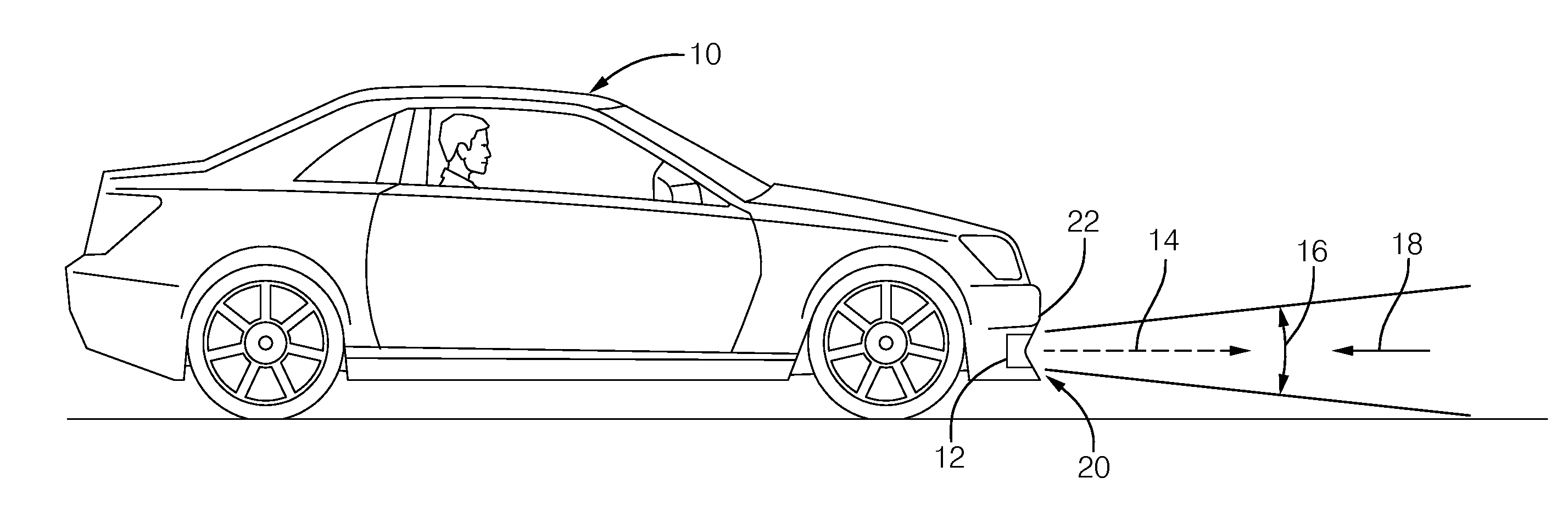
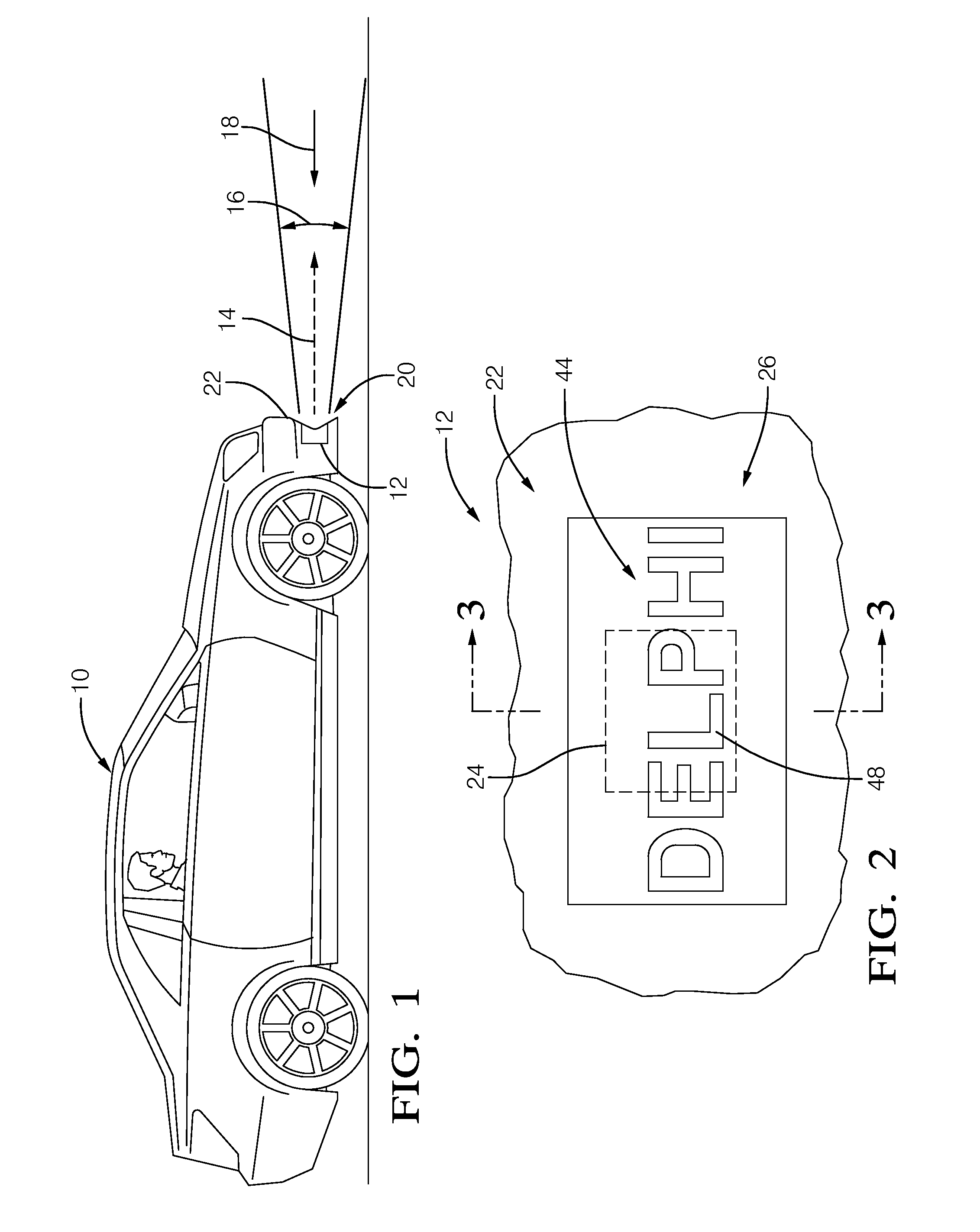
[0012]FIG. 1 illustrates a non-limiting example of a vehicle 10 equipped with a radar sensor assembly, hereafter the assembly 12. In general, the assembly is configured to project or emit a radar beam 14 toward a radar field of view 16 and receive a reflected radar signal 18 from the radar field of view 16, as is well known. The assembly 12 is illustrated as being part of a front bumper assembly 20 of the vehicle 10, in particular including part of a fascia 22 of the front bumper assembly. However, other locations on the vehicle (e.g. rear bumper assembly) and non-vehicle applications such as building security proximity detectors are contemplated.

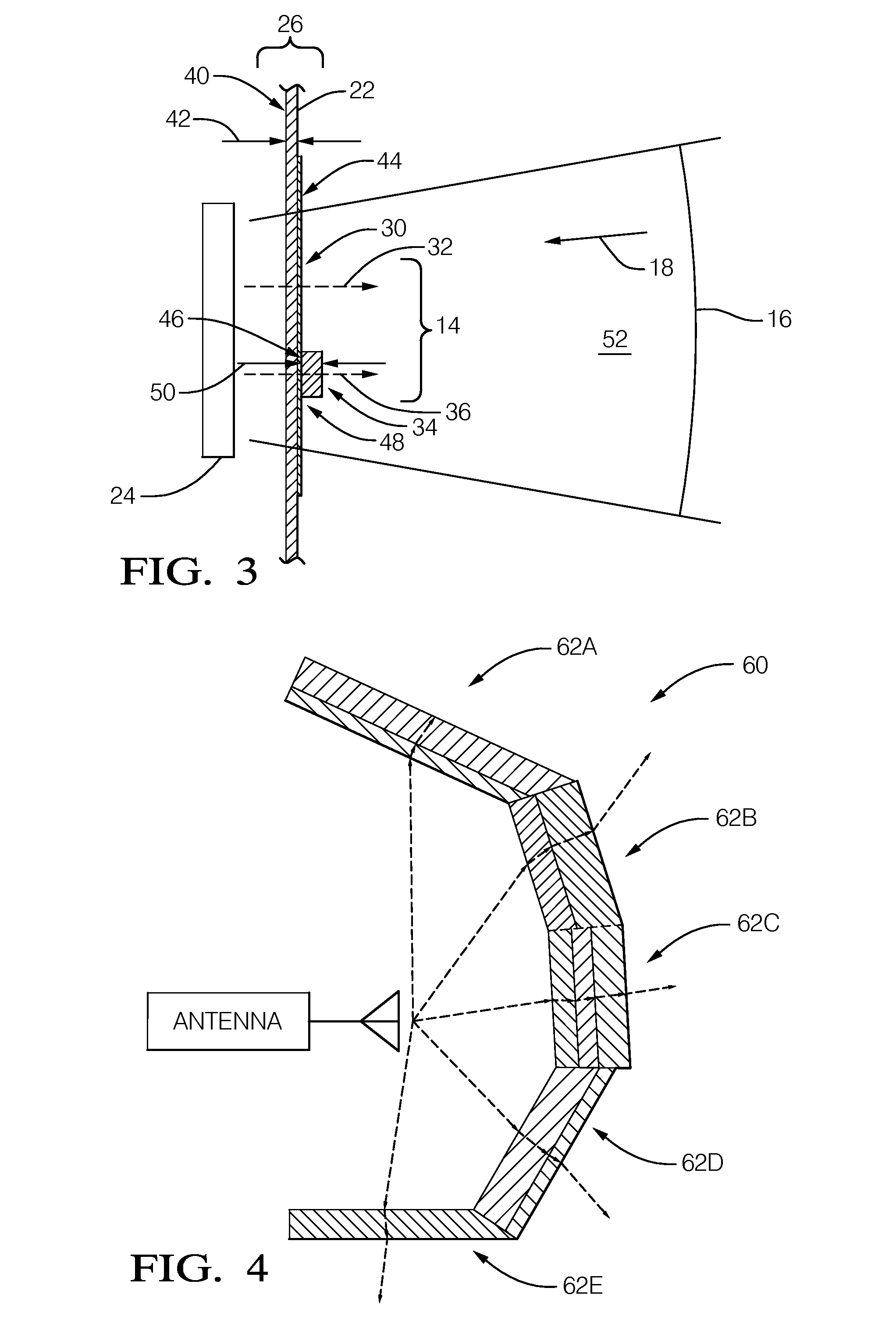
[0013]FIGS. 2 and 3 illustrate a non-limiting example of a front view and a sectional side view of the assembly 12. In general, the assembly 12 includes a radar sensor 24 configured to emit the radar beam 14 toward the radar field of view 16 and receive the reflected radar signal 18 from the radar field of view 16. By way of example and not...


PUM


Abstract

A radome for a radar sensor that includes a first and second section. Each section is formed of layers that have an electrical thickness substantially equal to an integer multiple of a guided half-wavelengths of the radar beam. Each of the sections are configured such that, at a location spaced apart from the radome, a first phase angle of the first portion of the radar beam differs from a second phase angle of the second portion of the radar beam by an amount substantially corresponding to an integer number of three hundred sixty degrees (360°) of phase angle shift.

Description

TECHNICAL FIELD OF INVENTION[0001]This disclosure generally relates to a radome for a radar sensor assembly, and more particularly relates to a radome that does not have uniform thickness, but does not distort the radar beam from the radar sensor.BACKGROUND OF INVENTION[0002]It is known to form a radome for a radar sensor using a uniform thickness layer of dielectric material. Using a uniform thickness avoids distorting the radar beam emitted by the radar sensor, and avoids distorting the reflected radar beam reflected by a target in the field of view of the radar sensor. In other words, it is desirable for the radome to be electromagnetically uniform. However, when a radar sensor is adapted for use on a vehicle, it may not be convenient or feasible to provide a uniform radome when the radome is part of the exterior of the vehicle. For example, it may be desirable to locate the radar sensor behind a fascia of a front bumper assembly on the vehicle to detect object in front the vehic...

Claims


Application Information

Patent Timeline
IPC IPC(8): H01Q1/42G01S13/02H01Q1/32
CPCH01Q1/421H01Q1/3233G01S13/02H01Q1/3283H01Q1/422G01S13/931G01S7/03G01S2013/93275G01S2013/93271G01S7/027
Inventor SHI, SHAWNVESS, DAVID JAY
Owner DELPHI TECH INC
Why Eureka
Try Eureka