
Systems and methods for 3D pose estimation

a technology of system and method, applied in the field of systems and methods for 3d pose estimation, can solve the problems of limited usability of application, inability to deal with significant illumination changes, and inability to use direct methods

Active Publication Date: 2014-04-03
AUGMENTED REALITY LAB
View PDF18 Cites 29 Cited by
  • Summary
  • Abstract
  • Description
  • Claims
  • Application Information

AI Technical Summary

Benefits of technology

The present system can estimate the position of an object in front of a camera by processing images from a single camera in real-time. This is done by detecting and matching significant visual features on the object in consecutive images. The system uses a 3D model of the object to approximate its shape, and can estimate the parameters of the object's position based on the degree of approximation of the model and the ability to track relevant features across images.

Problems solved by technology

Small errors in the 2D registration may be reflected in large misalignments of the 3D content.
The local features approach can only work on surfaces that are well textured which limits the usability of the application.
The methods using the direct approach tend to be computationally intensive and are typically unable to deal with significant illumination changes.
In addition, the approach has been limited in the number of degrees of freedom (DOF) that are available.
Thus, NFT methods limits tracking to highly-textured objects or environments in which prominent scene features can be robustly and quickly located in each frame.
NFT methods usually exhibit increased computational complexity compared with fiducial-based methods, as well as reduced accuracy, since little is assumed about the environment to be tracked.
Nevertheless, such methods are difficult to use for creating natural user-interfaces.
Although theoretically general, the construction proposed in Ruiz 2006 limits the scope of usable shapes by several assumptions on shape concavities, and limits the use of the method in AR applications.

Method used


Image

  • Systems and methods for 3D pose estimation
  • Systems and methods for 3D pose estimation
  • Systems and methods for 3D pose estimation

Examples


Embodiment Construction

[0022]The present system is a method of 3D pose estimation of an object using 3D modelling of an approximation of the object. The approximation may be parametric or non-parametric as desired.

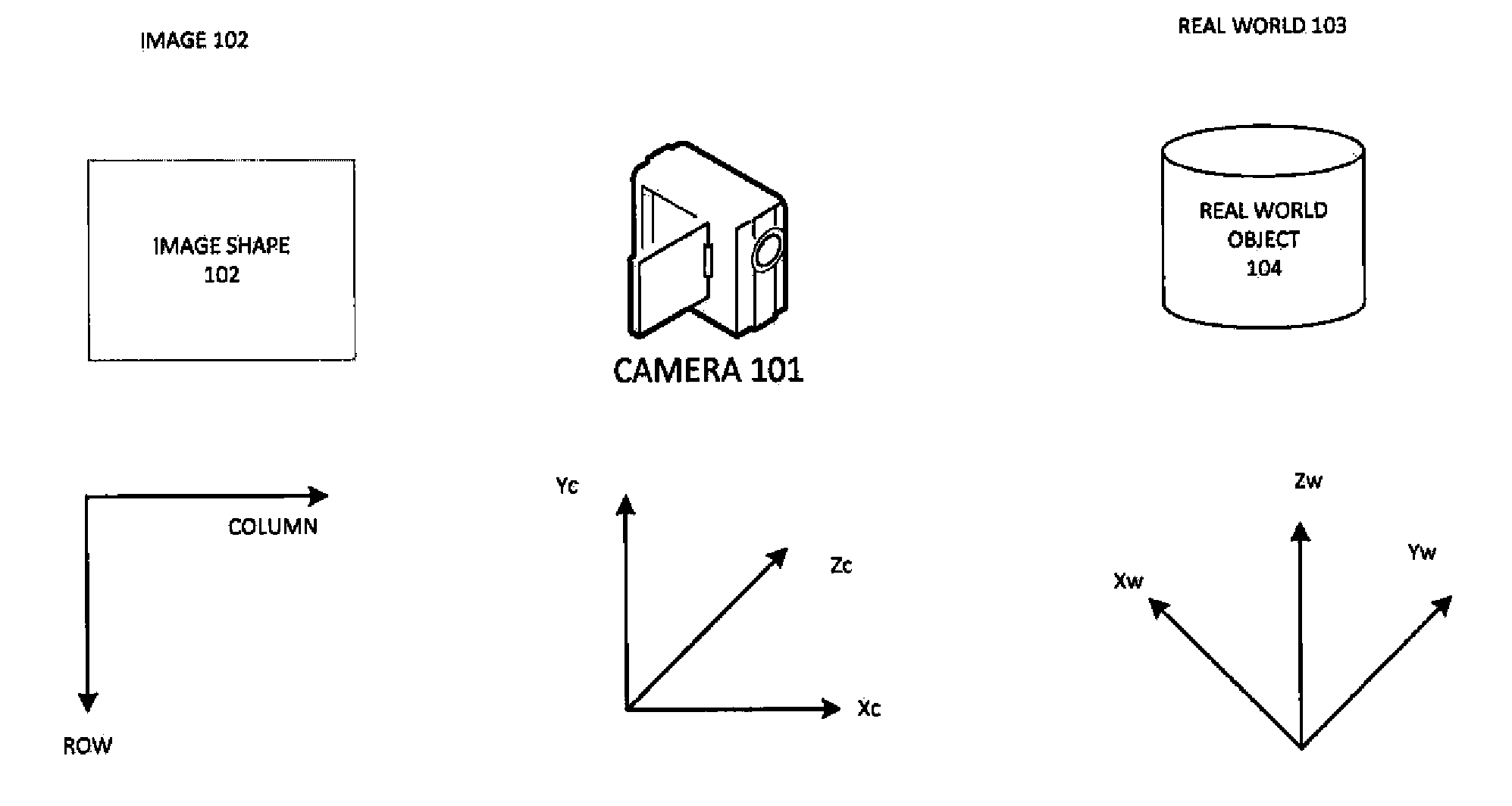
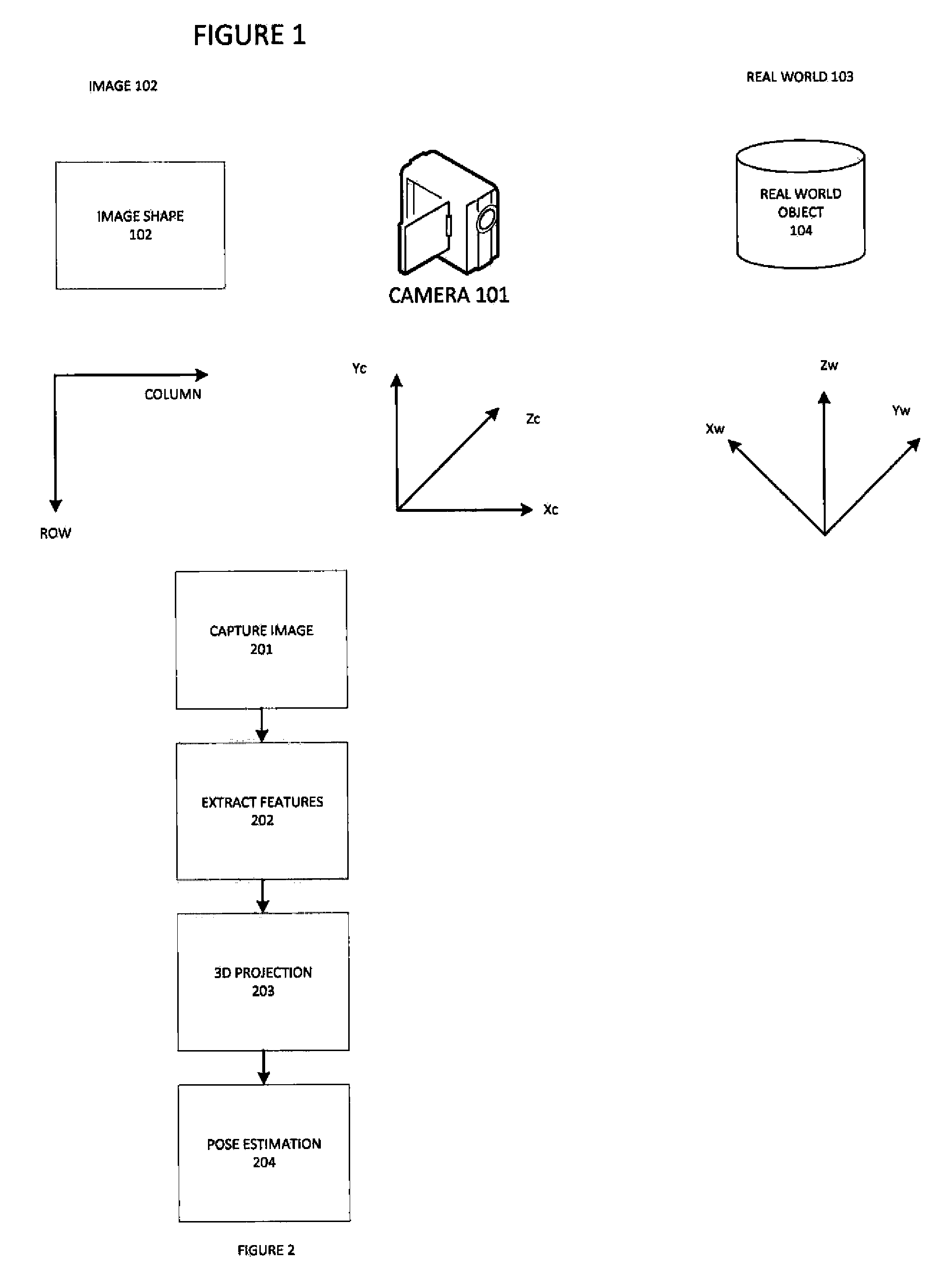
[0023]The system is implemented by an acquisition system (e.g. camera) capturing an image (2D image plane) of an object in the 3D world. Each of these actors has its own coordinate system as illustrated in FIG. 1. Referring now to FIG. 1 we see the camera 101 creating an image 102 from an object 104 in the real world 103. The image 102 is a 2D image plane comprised of pixels and having a coordinate system having an origin 0,0 at the upper left in one embodiment, with rows 105 and columns 106 defining an image frame.

[0024]The camera 101 is a video camera in one embodiment and operates in 3D space with 6DOF in the Xc, Yc, Zc coordinate system. The object of interest 104 is in the 3D real world and has a coordinate system in the Xw, Yw, Zw coordinate system. The camera and real world coordinate sys...


PUM


Abstract

The present system provides a tool to estimate the relative pose of a generic object with respect to a camera view-point by processing 2D images from a monocular camera in real-time. The capability of solving the pose estimation problem relies on the robust detection and matching in consecutive image frames of significant visual features belonging to an object of interest. To accomplish this, the system incorporates 3D modeling of the object of interest. In one embodiment, the shape of interest may be approximated by a parametric surface such as a cylinder, sphere, ellipsoid, or even complex non-parametric models. The system can restrain information retrieved at a 2D image level to estimate parameters about the pose. In operation, the accuracy of the 3D pose estimation of the object is a function of the degree of approximation of the selected model and the ability to select and track relevant features across consecutive image frames.

Description

BACKGROUND[0001]It is sometimes desired to allow a person to combine virtual reality with a real world surface. For example, a user may point the camera of a computer or smart-phone or tablet at a wall and the wall will appear on the display of the camera device. In addition, some virtual object will appear in the image as well, and appear as if it is part of the real world environment, such as, for example, a basketball hoop appearing to be affixed to the wall. The virtual content may include labels, 3D models, shading, illumination, and the like This is referred to as Augmented Reality (“AR”). In order for the view of the real world and the virtual scene to align properly (i.e. to be properly registered), the pose (i.e. 3D position and orientation) and other properties of the real and virtual cameras must be the same.[0002]Estimating the pose of an object relative to the real world is a task of an AR system. Many different AR tracking methods and systems are available in the curre...

Claims


Application Information

Patent Timeline
IPC IPC(8): G06T19/00
CPCG06T19/006G06T2207/10016G06T7/74G06T7/75G02B27/017G06T19/00G06F3/012
Inventor ISSA, FRIDAGARCIA-MORATO, PABLO
Owner AUGMENTED REALITY LAB
Learn More