Image display apparatus and image adjustment method of image display apparatus

Active Publication Date: 2014-04-03
SEIKO EPSON CORP
View PDF3 Cites 2 Cited by
  • Summary
  • Abstract
  • Description
  • Claims
  • Application Information

AI Technical Summary

Benefits of technology

The invention provides an image display apparatus and method that can correct the linearity of images using a curved surface shape. This is achieved by adjusting the positions of indexes on a test pattern displayed on the surface. The position adjustment can be done while watching the test pattern, making it easy for the user to visually grasp the correction process. The indication of the indexes is preferred to be a linear shape, such as a straight line or dot, to make the movement and intervals between the indexes easier for the user to understand. The technical effect of the invention is to simplify the process of correcting image linearity for users.

Problems solved by technology

However, in the case of correcting the linearity using the scanning image display apparatus described above, there is a problem that it is difficult for the user to visually figure out how the linearity of the image is actually corrected.

Method used


Image

  • Image display apparatus and image adjustment method of image display apparatus
  • Image display apparatus and image adjustment method of image display apparatus
  • Image display apparatus and image adjustment method of image display apparatus

Examples


Embodiment Construction

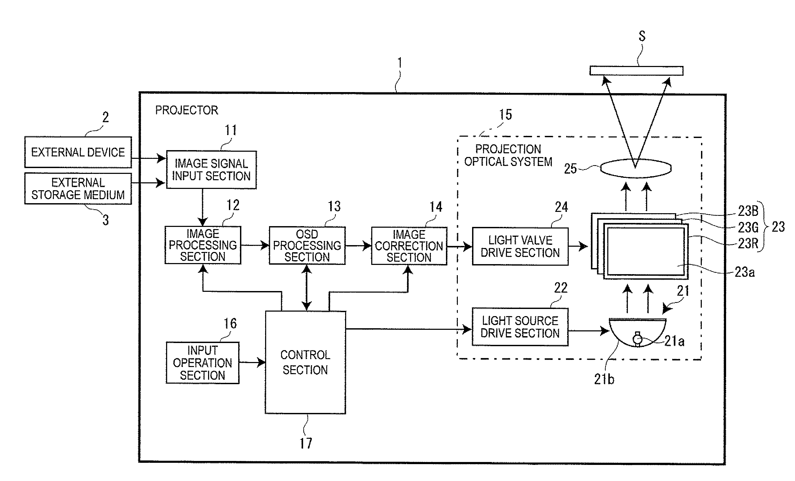
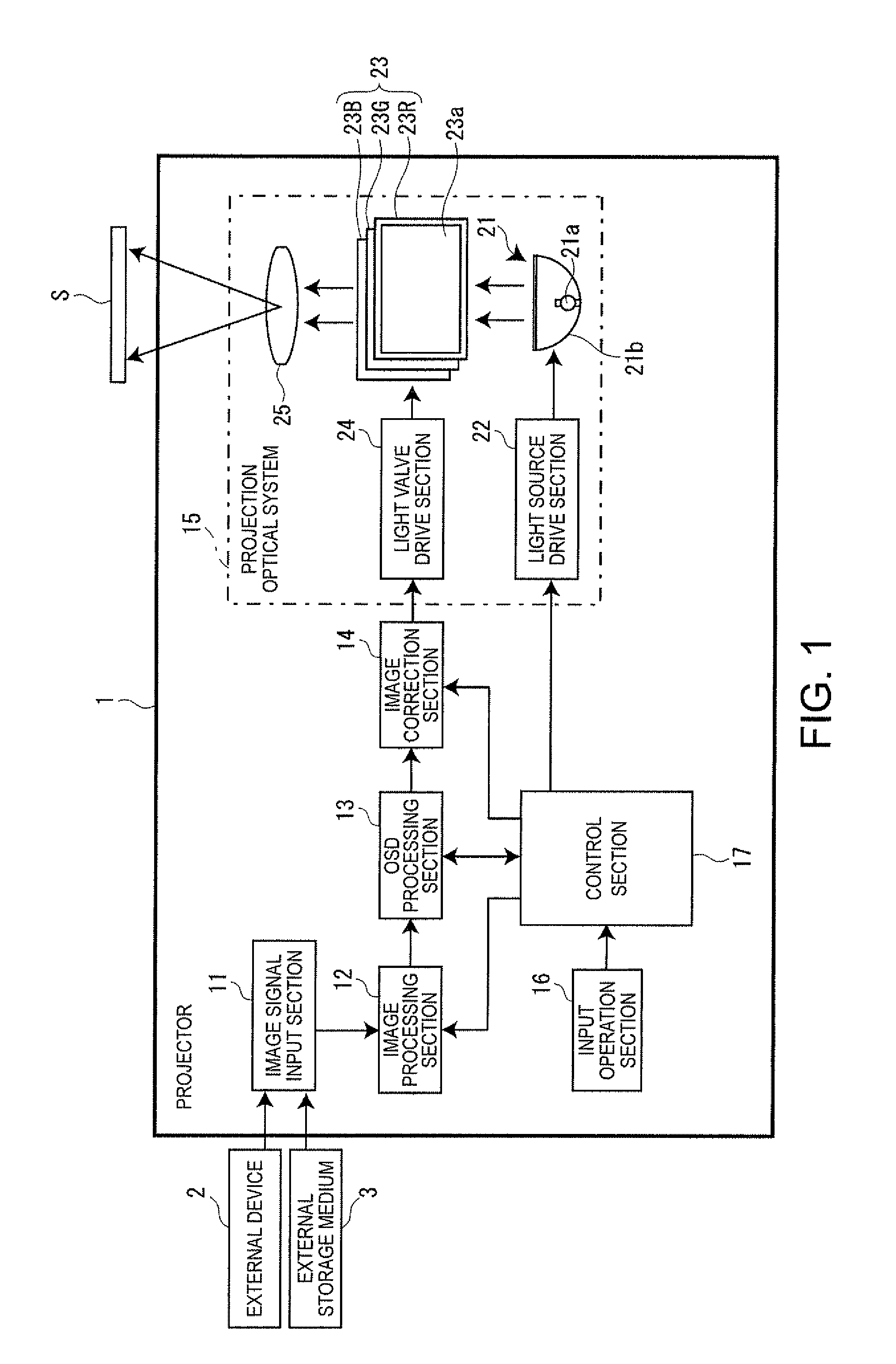
[0029]An image display apparatus and an image adjustment method of an image display apparatus according to an embodiment of the invention will hereinafter be explained with reference to the accompanying drawings. As an example of the image display apparatus according to the present embodiment, a projector 1 will be explained. FIG. 1 is a block diagram showing a configuration of the projector 1. As shown in the drawing, the projector 1 is provided with an image signal input section 11, an image processing section 12, an OSD processing section 13, an image correction section 14 (a linearity correction section), a projection optical system 15, an input operation section 16, and a control section 17 for controlling these sections.

[0030]The image signal input section 11 gets image information (an image signal) from an external device 2 such as a personal computer or a DVD player, or an external storage medium 3 such as a USB memory or a compact flash (a registered trade mark) memory card...


PUM


Abstract

An image display apparatus includes an OSD processing section that displays a test pattern, which includes a plurality of index lines arranged in one of horizontal and vertical directions with respect to a pixel area of a liquid crystal light valve at regular intervals, in the pixel area, an input operation section that sets at least one of the plurality of index lines as a reference index line, and adjusts the intervals of the index lines of the test pattern so as to increase or decrease as a distance from the reference index line increases with respect to the direction of the arrangement of the index lines taking the reference index line as a reference, and an image correction section that corrects linearity of the image based on the intervals of the index lines adjusted by the input operation section.

Description

CROSS-REFERENCE TO RELATED APPLICATION[0001]The entire disclosure of Japanese Patent Application No. 2012-220251, filed Oct. 2, 2012 is expressly incorporated by reference herein.BACKGROUND[0002]1. Technical Field[0003]The present invention relates to an image display apparatus for displaying an image on an image display surface, and an image adjustment method of the image display apparatus.[0004]2. Related Art[0005]In the past, there has been known a scanning image display apparatus capable of correcting the linearity (nonlinearity distortion) of an image projected on a screen. In, for example, JP-A-2007-199251, as a method of correcting the vertical linearity, there is disclosed a method of obtaining a pitch θp of a field angle in the vertical direction, with which a pitch ratio Ryp of the scan image is always constant with respect to a pitch count n obtained by counting the pitch upward from the polarized light beam reaching the center of the scan image, and driving a vertical po...

Claims


Application Information

Patent Timeline
IPC IPC(8): G06T5/00
CPCG06T5/006H04N9/3185G06T5/80H04N9/3135H04N9/3191H04N9/3197
Inventor YOSHIMURA, JUNKOBAYASHI
Owner SEIKO EPSON CORP
Why Eureka
Try Eureka