Mixed control method for resonant converter, resonant converter system and mixed controller

a technology of resonant converter and mixed control method, which is applied in the direction of electric variable regulation, process and machine control, instruments, etc., can solve the problems of resonant converter, frequency changing control, and increase of circuit loss

Active Publication Date: 2014-04-03
DELTA ELECTRONICS INC
View PDF4 Cites 16 Cited by
  • Summary
  • Abstract
  • Description
  • Claims
  • Application Information

AI Technical Summary

Benefits of technology

[0042]It can be seen from the above technical solutions that, the present application has the following advantageous effects: when a resonant converter operates in a case where a voltage gain is less than a predetermined value, it is easy to realize a relatively low voltage gain and a small circuit loss, thereby improving circuit efficiency.

Problems solved by technology

Although the resonant converters have advantages, such as high conversion efficiency, under a normal operation state, i.e., under a situation where a voltage gain is greater than or equal to a predetermined value, there are still some problems existing in the resonant converter which only employs frequency changing control when it operates under an abnormal operation state, e.g., when the voltage gain is less than the predetermined value (e.g., under a state where the circuit is started or an output current is limited or the like).
However, an increase of frequency means an increase of circuit loss.
The above control method of only changing frequency cannot resolve the problem of overlarge circuit loss which occurs when the voltage gain is less than the predetermined value.
However, a hard-switching of switches at primary side may be brought out by reducing the pulse width, thereby resulting in that the entire loss is still large.

Method used


Image

  • Mixed control method for resonant converter, resonant converter system and mixed controller
  • Mixed control method for resonant converter, resonant converter system and mixed controller
  • Mixed control method for resonant converter, resonant converter system and mixed controller

Examples


Embodiment Construction

[0059]Specific embodiments of the present application will be described below in detail. It should be noted that, the embodiments described here are only for illustration but not to limit the present application. Furthermore, in the following description, “an embodiment” or “embodiment” that appears in different parts does not necessarily refer to the same embodiment. In addition, particular features, structures or characteristics in one or more embodiments may be combined in any suitable form.

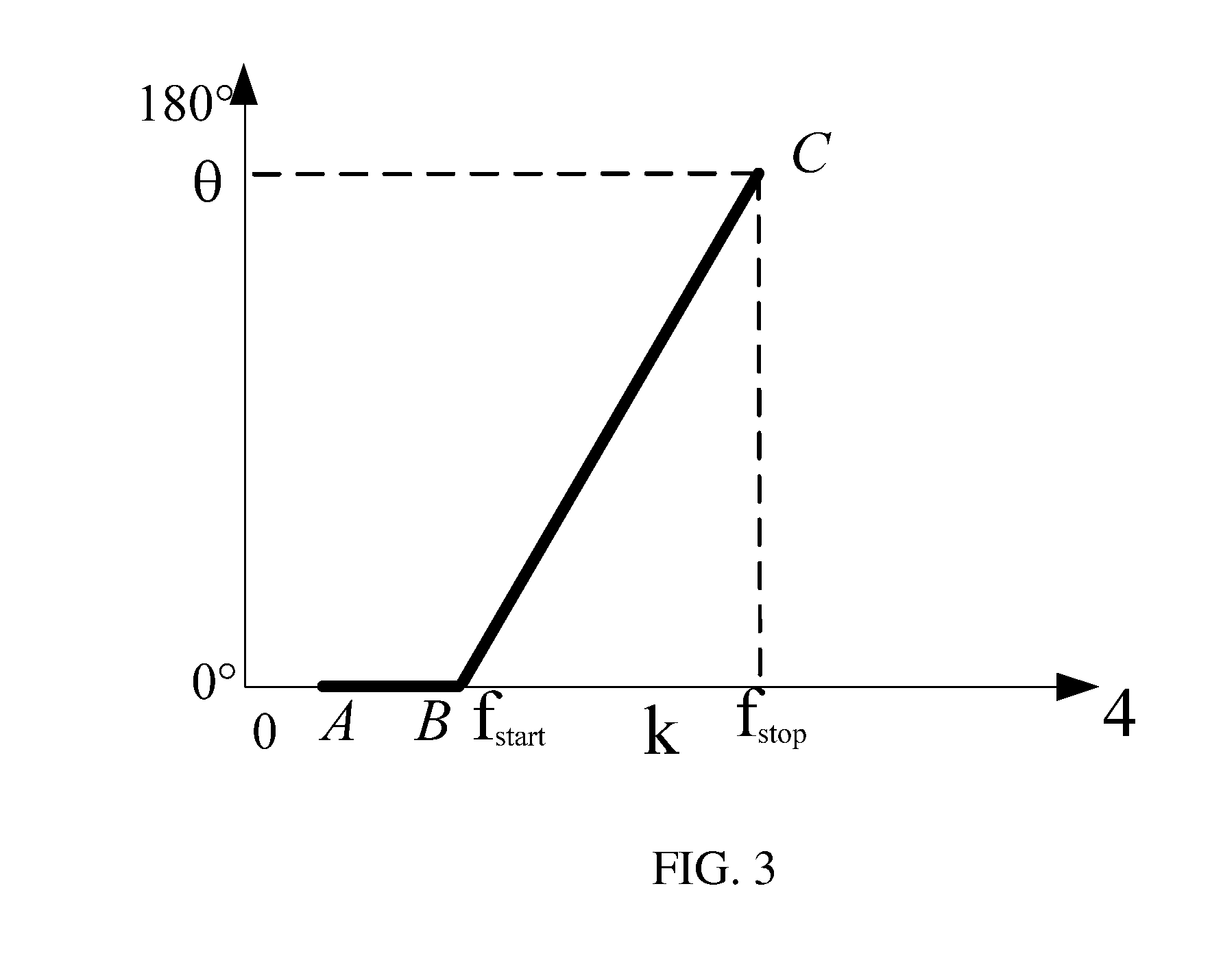
[0060]FIG. 3 is a schematic diagram illustrating a mixed control method for a resonant converter with phase shifting and frequency changing according to an embodiment of the present application, where the abscissa represents a ratio k (hereinafter referred to as a frequency ratio) of an operating frequency f of the resonant converter to a resonant frequency Fs of the resonant circuit, and the ordinate represents a phase-shifting angle θ. In the present embodiment, the method includes two contr...


PUM


Abstract

The present application provides a mixed control method for a resonant converter, a resonant converter system and a mixed controller. When the resonant converter operates in a case where a voltage gain is less than a predetermined value, the method includes: setting a mixed control start frequency, a mixed control stop frequency and a slope of a phase-shifting angle; detecting an operating frequency of the converter; calculating a time delay of phase shifting according to the slope, the mixed control start frequency, the mixed control stop frequency and a resonant frequency of the resonant converter; and according to the time delay, the mixed control start and stop frequencies, generating a control signal to adjust the operating frequency and the phase-shifting angle of the resonant converter. The present application can realize a relatively low voltage gain and a small circuit loss, thereby the circuit efficiency may be improved.

Description

TECHNICAL FIELD[0001]The present application relates to a type of controlling for resonant converters, specifically, to a mixed control method for a resonant converter, a resonant converter system and a mixed controller.BACKGROUND[0002]Like most of the power supply products, DC / DC converters are developing towards high efficiency, high power density, high reliability and low cost. Since resonant converters usually employ a control method of Pulse Frequency Modulation (PFM), it is relatively easy to realize a zero voltage switching of switches therein and it is easy to meet the high efficiency and high power density requirements for converters. Thus, the resonant converters are widely used.[0003]Although the resonant converters have advantages, such as high conversion efficiency, under a normal operation state, i.e., under a situation where a voltage gain is greater than or equal to a predetermined value, there are still some problems existing in the resonant converter which only emp...

Claims


Application Information

Patent Timeline
Patent Type & Authority Applications(United States)
IPC IPC(8): H02M3/335
CPCH02M3/33507H02M3/3376H02M1/0058Y02B70/10Y02P80/10
Inventor YAN, CHAOYAN, LIHAO
Owner DELTA ELECTRONICS INC
Why Eureka
Try Eureka