Gain control circuit and its gain control method

a gain control circuit and gain control technology, applied in the field of control technology, can solve problems such as serious distortion, and achieve the effect of preventing the distortion of the output signal of the audio amplifier circui

Inactive Publication Date: 2011-06-21
TAI 1 MICROELECTRONICS CORP
View PDF3 Cites 2 Cited by
  • Summary
  • Abstract
  • Description
  • Claims
  • Application Information

AI Technical Summary

Benefits of technology

[0007]A major objective of the present invention is to provide a gain control circuit and its gain control method, that is realized through adjusting a ramp wave signal DC voltage level, such that not only the output signal distortion of audio amplifier circuit can be prevented, but the magnitude of output signal of an audio amplifier circuit can also be restricted, thus protecting a loudspeaker or human ears from being damaged.
[0008]In order to achieve the above mentioned objective, the present invention provides a gain control circuit connected to an amplifier circuit, and that is used to output an output signal, comprising: a processor, a ramp wave signal generator, a counter, a voltage detector, and a DC voltage level regulator. Wherein, the counter is used to output a counter value continuously, and is connected to a ramp wave signal generator; the ramp wave signal generator outputs a ramp wave signal based on the counter value, and when the ramp wave signal generator is a trigonometric wave signal generator or a saw-tooth wave signal generator, then the ramp wave signal output by the ramp wave signal generator is a trigonometric wave signal or a saw-tooth wave signal. The amplifier circuit and the counter are connected respectively to a processor. The processor receives the ramp wave signal and a control voltage signal, and obtains from the counter a counter value corresponding to the ramp wave signal as the first counter value and stores it temporarily, at a voltage that the control voltage signal intersects the ramp wave signal, and determines the magnitude of voltage gain of an amplifier circuit based on the first counter value. In addition, a voltage detector is provided, which presets detection voltage upper and lower limits, receives an output signal, and outputs a detector signal when the high voltage of the output signal is greater than the detection voltage upper limit or when the low voltage of the output signal is less than the detection voltage lower limit. The ramp wave signal generator and the voltage detector are connected respectively to a DC voltage level regulator, that is used to receive a detection signal to regulate the DC voltage level of a ramp wave signal, such that the counter value obtained by the processor from the counter is corresponding to the ramp wave signal and less than the first counter value, and that serves as a second counter value in updating the first counter value, hereby reducing the voltage gain of the amplifier circuit by using the second counter value.
[0009]Furthermore, the present invention provides a gain control method, wherein, an output signal output by an amplifier circuit is received and is used to control the magnitude of voltage gain of the amplifier circuit, comprising the following steps: firstly, outputting continuously a counter value by a counter; next, generating a ramp wave signal by a ramp wave signal generator based on the counter value; then, receiving by a processor the ramp wave signal and a control voltage signal, and at a voltage of the control voltage signal intersecting the ramp wave signal, obtaining from the counter a counter value corresponding to the ramp wave signal as the first counter value and storing it temporarily, and determining an initial voltage gain of the amplifier circuit based on the first counter value; subsequently, upon determining the initial voltage gain, in case that the high voltage of an output signal is greater than a preset detection voltage upper limit or in case that the low voltage of an output signal is less than a preset detection voltage lower limit, then outputting a detection signal by a voltage detector, and upon receiving the detection voltage by a DC voltage level regulator, regulating the DC voltage level of the ramp wave signal; and finally, receiving by the processor from the counter the counter value, that is corresponding to the ramp wave signal and less than the first counter value, and that serves as a second counter value in updating the first counter value, as such reducing the initial voltage gain of the amplifier circuit by using the second counter value.

Problems solved by technology

However, under a specific voltage gain, in case that the voltage of an input signal of an amplifier circuit 10 is overly large, then the voltage of the signal output by the amplifier circuit 10 may exceeds a rated voltage, thus creating serious distortion.

Method used


Image

  • Gain control circuit and its gain control method
  • Gain control circuit and its gain control method
  • Gain control circuit and its gain control method

Examples


first embodiment

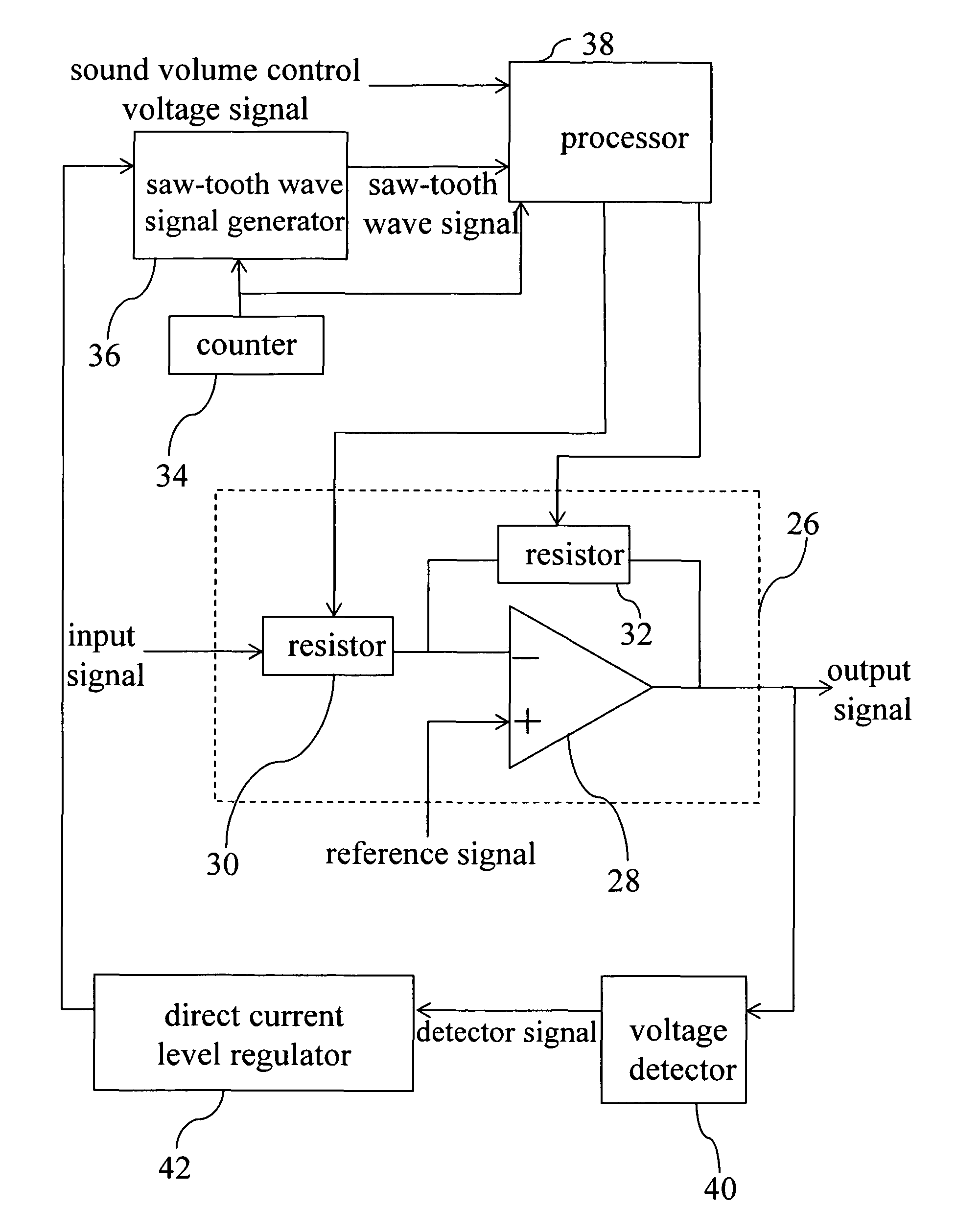
[0025]Refer to FIG. 3, FIGS. 4(a) and 4(b) simultaneously. Wherein, FIG. 3 is a circuit diagram of a gain control circuit according to the present invention; FIG. 4(a) is the waveform diagram of the output signal of a counter; and FIG. 4(b) shows the waveform diagrams of sound volume control voltage signal and positive slope saw-tooth wave signal according to an embodiment of the present invention. In the present invention, the gain control circuit is connected to an audio amplifier circuit 26, such that the audio amplifier circuit 26 includes an amplifier 28, a resistor 30, a resistor 32. The positive input terminal of the amplifier 28 is used to receive a reference signal, with its negative terminal connected to a resistor 30 and a resistor 32, and is used to receive an input signal. The output terminal of the amplifier 28 is connected to a resistor 32, such that the input signal is amplified by the amplifier 28, and then is output from an output terminal of the amplifier 28. Sinc...

second embodiment

[0040]In the following, the present invention will be described, and a positive slope saw-tooth wave signal is taken as an example for explanation. Refer to FIG. 7, FIGS. 8(a) to 8(c), and FIG. 9 simultaneously. Wherein, FIG. 8(a) is a waveform diagram of output signal of a counter; FIG. 8(b) shows the waveform diagrams of sound volume control voltage signal and positive slope saw-tooth wave signal; and FIG. 8(c) is a waveform diagram of a latch-up signal.

[0041]Before a time point t2, a sound volume control voltage signal is intersected with a saw-tooth wave signal at a voltage Va, that corresponds to time point t1 in a first periodic waveform of a saw-tooth wave signal, therefore, at this time point, the comparator 44 will output a first latch-up signal to a status register controller 46, so that the status register controller 46 will obtain from a counter 34 a counter value 100, that corresponds to a voltage Va of the saw-tooth wave signal, and that serves as the first counter val...


PUM


Abstract

A gain control circuit and its gain control method, said gain control method comprising the following steps: firstly, outputting continuously a counter value; next, generating a ramp wave signal based on said counter value, and at a voltage where a control voltage signal intersects said ramp wave signal, obtaining an initial counter value based on said ramp wave signal, thus determining an initial voltage gain of an amplifier circuit; then, when a high or low voltage of an output signal of said amplifier circuit is greater or less than a predetermined detection voltage upper or lower limit, adjusting a DC voltage level of said ramp wave signal with a detection signal; and finally, obtaining at said voltage a counter value less than said initial counter value based on said ramp wave signal, hereby reducing said initial voltage gain based on said counter value.

Description

BACKGROUND OF THE INVENTION[0001]1. Field of the Invention[0002]The present invention relates to a control technology, and in particular to a gain control circuit and its gain control method.[0003]2. The Prior Arts[0004]In general, an analog type electronic gain control circuit is achieved through a Golbert cell. The basic conversion characteristic of Gilbert cell is Y=kX, wherein, Y is an output signal voltage, X is an input signal voltage, and k is a constant. From the above equation it is evident that, its amplification factor or voltage gain can be set at Y / X, and Y / X=k. Therefore, k is the voltage gain of output signal voltage Y relative to input signal voltage X.[0005]In the following descriptions, refer to FIG. 1&FIGS. 2(a) to 2(c) simultaneously. Compared with an analog type electronic gain control circuit, a digital type electronic gain control circuit has a wider dynamic operation range and more accurate control relative to an audio amplifier circuit 10. Wherein, FIG. 2(a)...

Claims


Application Information

Patent Timeline
Patent Type & Authority Patents(United States)
IPC IPC(8): H03G3/20
CPCH03G3/301H03G3/001
Inventor TAI, JY-DER DAVID
Owner TAI 1 MICROELECTRONICS CORP
Why Eureka
Try Eureka