
Method for identifying a seismic event and a seismic detector for implementing same

Inactive Publication Date: 2014-04-03
ANGRYMOLE TECH
View PDF4 Cites 9 Cited by
  • Summary
  • Abstract
  • Description
  • Claims
  • Application Information

AI Technical Summary

Benefits of technology

The invention provides a method for recognizing seismic events and determining the direction of the seismic disturbance source both on surface and in three-dimensional space. This improves the likelihood of correct recognition and accuracy of direction determination. A compact seismic detector is also provided, reducing deployment and servicing costs. The method involves calculating time shifts and cross-correlation power between sensors, and a multi-channel integrator is used to increase the accuracy of event recognition. Overall, the invention provides an efficient and cost-effective solution for perimeter security.

Problems solved by technology

Disadvantage of this kind of the systems is that detectors do not determine the direction to disturbance source, therefore it is impossible to identify, where the event took place—within the protected zone or beyond its boundaries.
Disadvantage of the system shortage is that, to ensure the functioning of the system, the lower sensor is buried at a depth of about 3-6 m, which makes the installation work much more expensive.
Disadvantage of the said device is the presence of additional technical means for generation of the reference seismic disturbance and measurement of the velocity of the seismic wave from this disturbance.
Another disadvantage of the device is that it doesn't determine the direction to the underground seismic disturbance source.

Method used

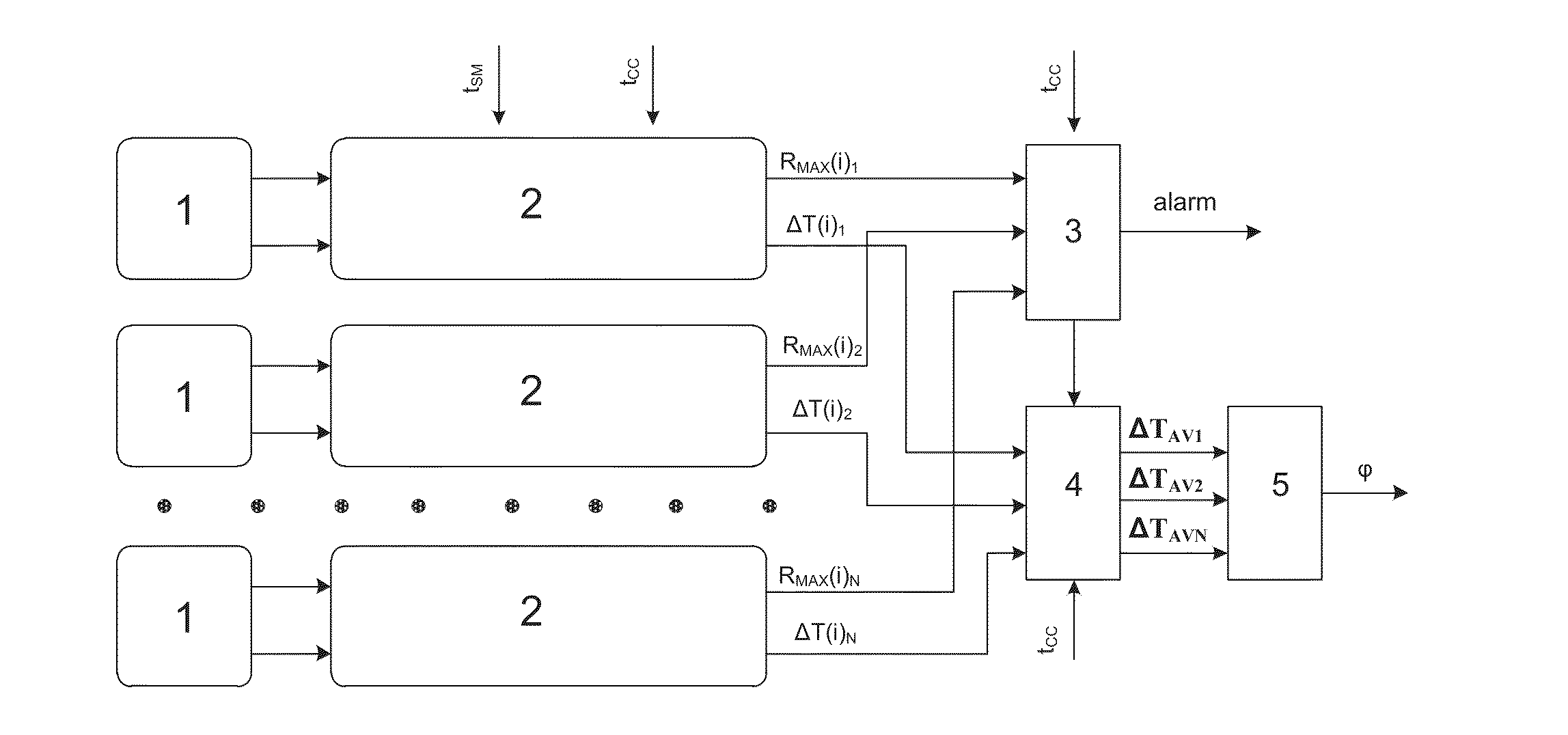
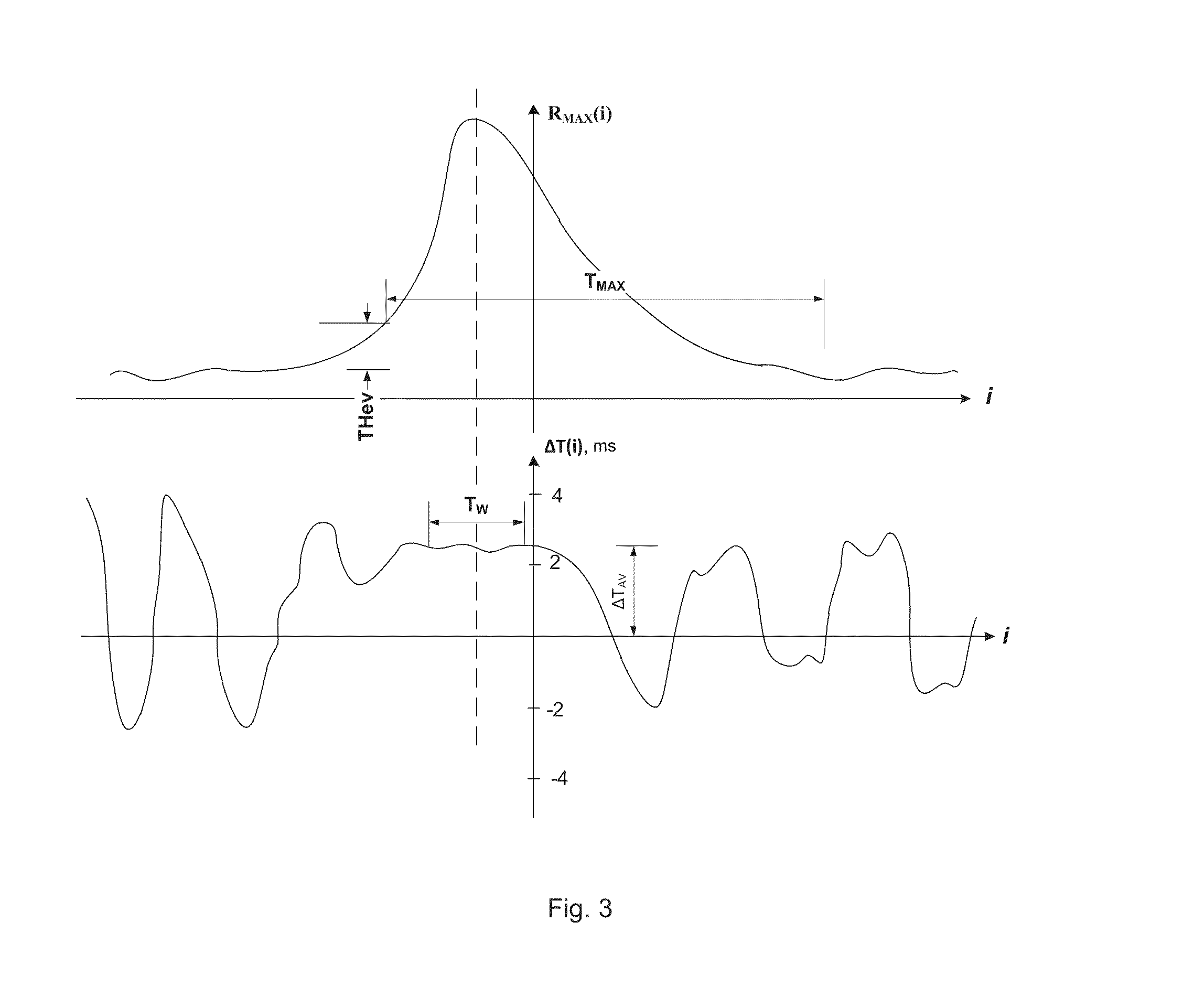

Image

  • Method for identifying a seismic event and a seismic detector for implementing same
  • Method for identifying a seismic event and a seismic detector for implementing same
  • Method for identifying a seismic event and a seismic detector for implementing same

Examples


Embodiment Construction

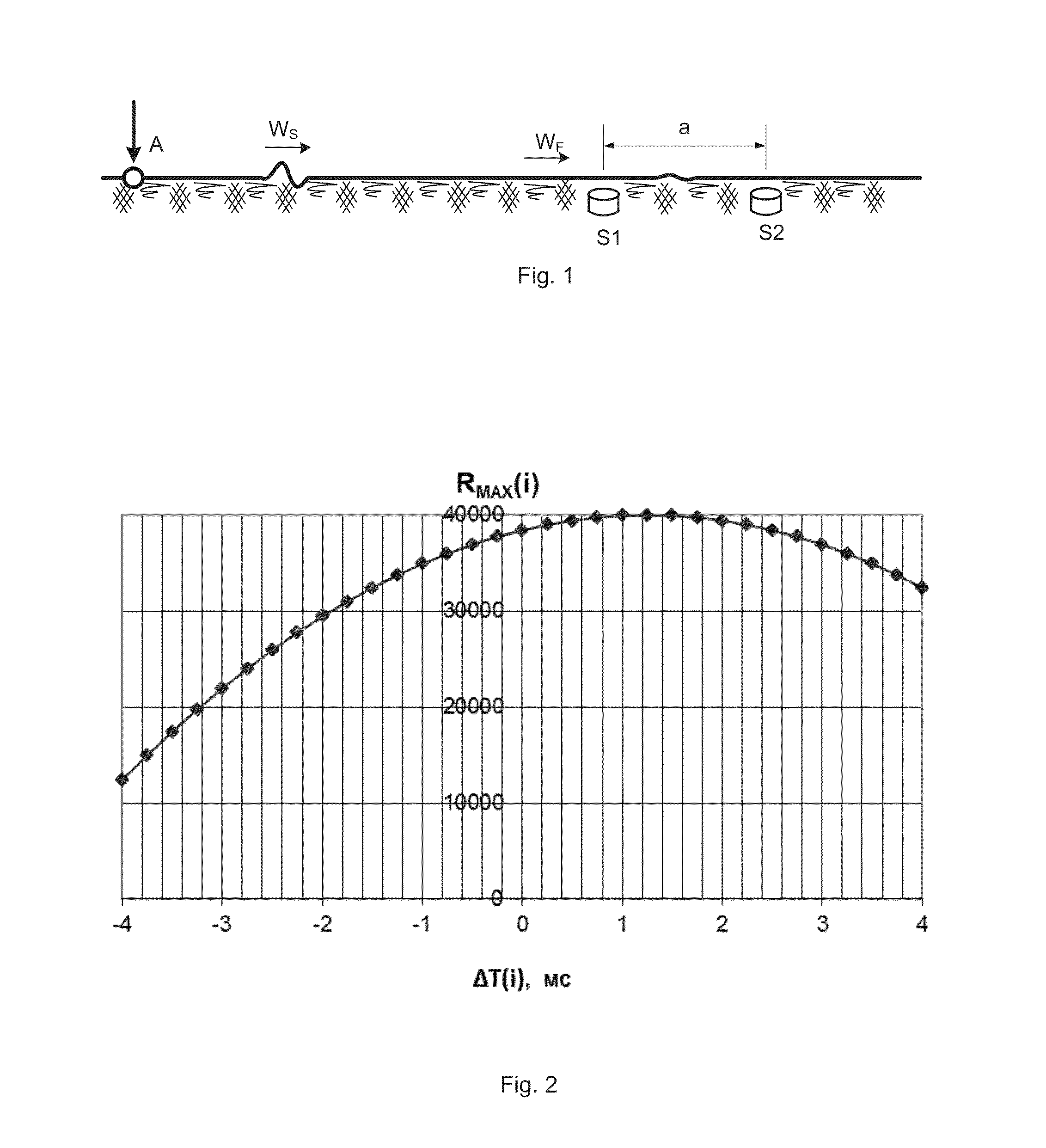
[0041]The basis of the detector (FIG. 1 ) is the pair of sensors S1 and S2. In the course of seismic disturbance, there are volume and surface elastic waves. It is known that the velocity of longitudinal volume waves is approximately by 1.7 times more than the velocity of transversal volume waves and surface waves; therefore, we will conditionally refer to the longitudinal volume waves as the fast wave (WF), and the remaining waves as the slow wave (WS). Besides, it is known that the transversal volume wave attenuates faster than the surface waves; therefore, the slow wave basically consists of surface waves. It is established in practice that the velocity of a slow wave in clay or sandy soil is about (100-300) m / s and that of the fast wave about (200-500) m / s. It is established in practice that the slow wave WS carries the main portion of the wave energy, about 70%; therefore, it propagates much further than the fast wave WF. Therefore, unlike the fast wave, the slow wave is always...


PUM


Abstract

A method for identifying a seismic even makes it possible to determine the direction to a source of a seismic disturbance both on the surface and in a three-dimensional space and increases the probability of correct identification of a seismic event and the accuracy of the determination of the direction to the source. A compact seismic detector for implementing the method reduces the cost of scanning and servicing a perimeter protection system constructed on the basis of such detectors. In the method, two or three pairs of seismic sensors which are divided by a distance and are oriented at an angle with respect to one another, for example mutually perpendicularly along the axes X, Y or along the axes X, Y, Z, respectively, are combined to form one seismic detector. The resultant seismic data are processed to determine the direction to the source of the seismic disturbance.

Description

RELATED APPLICATIONS[0001]This Application is a Continuation application of International Application PCT / RU2011 / 000510, filed on Jul. 11, 2011, which in turn claims priority to Russian Patent Applications No. RU 2011123387, filed Jun. 9, 2011, both of which are incorporated herein by reference in their entirety.FIELD OF THE INVENTION[0002]The invention pertains to the area of technical means and methods of protection and can be used for detection of moving trespassers at a distance of up to 40 meters by their seismic signals for protection of territories and access ways to various facilities.[0003]Steps of human or big animals and impacts of digging tool (pick, shovel etc.) are understood as the seismic disturbances recognized by the detector as a seismic event. The event is considered detected if the signal level exceeds a preset value. The alarm signal is thus generated.BACKGROUND OF THE INVENTION[0004]The systems, built on the basis of simple detectors (U.S. Pat. No. 4,001,771, ...

Claims


Application Information

Patent Timeline
IPC IPC(8): G01V1/00
CPCG01V1/001G01V1/288G08B21/10
Inventor BAGRATASHVILI, NODARI V.
Owner ANGRYMOLE TECH
Learn More