Book Coil Binding Machine

a coil binding machine and coil binding technology, applied in the field of book binding instruments, can solve the problems of manual operations that must delay the binding procedure, disadvantage to mass production, complicated structure, etc., and achieve the effects of simple structure, enhanced binding efficiency, and simple operation

Inactive Publication Date: 2014-04-03
CHUNG SHEEN TECH
View PDF7 Cites 2 Cited by
  • Summary
  • Abstract
  • Description
  • Claims
  • Application Information

AI Technical Summary

Benefits of technology

[0008]Another objective of this invention is to provide a book coil binding machine which is able to enhance the efficiency of binding the books with the coils.
[0009]Further an objective of this invention is to provide a book coil binding machine which is able to enhance the yield of binding the books with the coils.
[0010]Yet an objective of this invention is to provide a book coil binding machine which has a simple structure, low manufacturing costs and easy operations.

Problems solved by technology

However, since the books are printed in large quantities, the manual operations must delay the binding procedures and be disadvantageous to mass production.
However, the machines still have disadvantages of the complicated structure and the unfavorable working efficiency and yield, which should be improved.

Method used


Image

  • Book Coil Binding Machine
  • Book Coil Binding Machine
  • Book Coil Binding Machine

Examples


Embodiment Construction

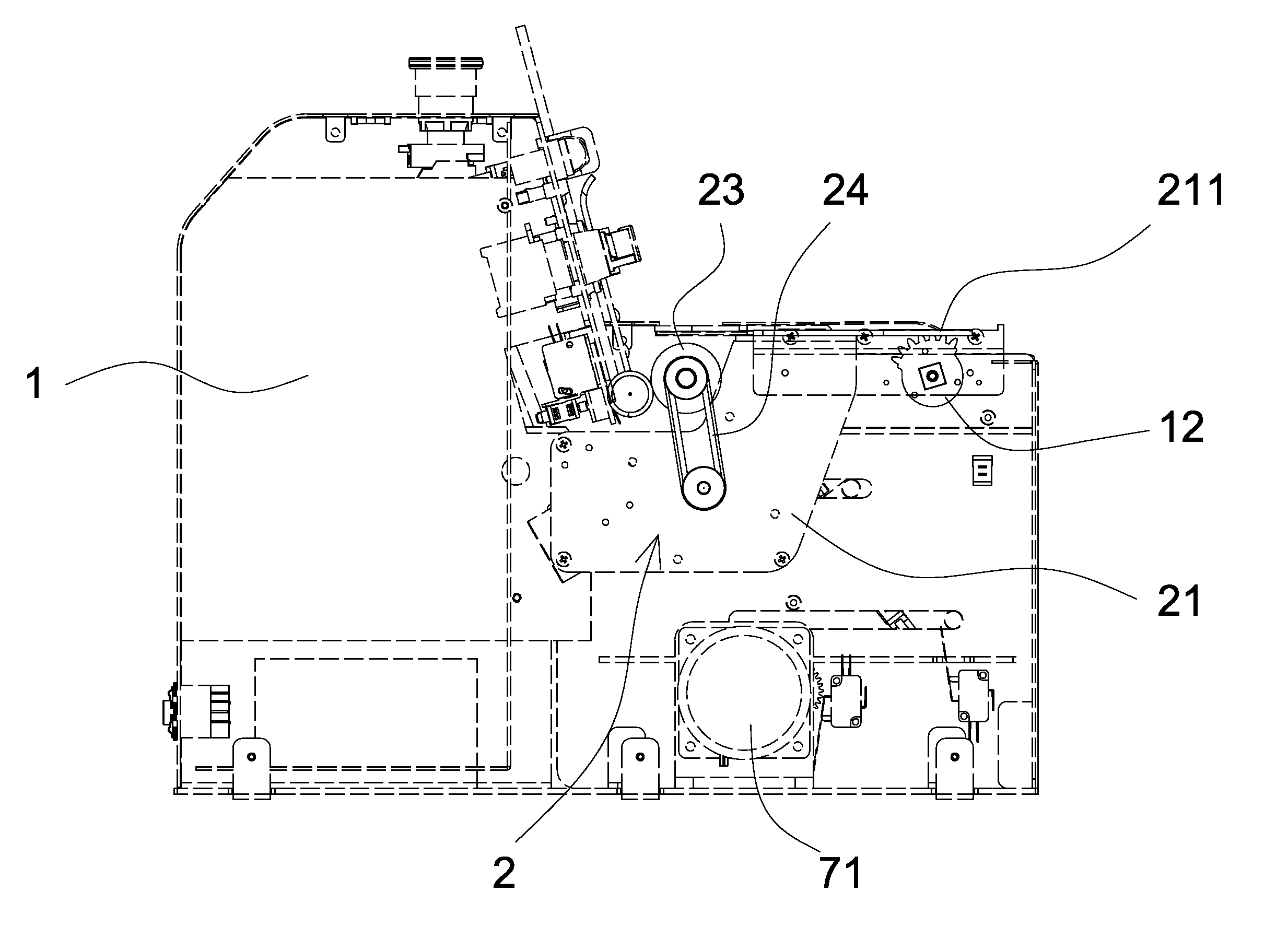
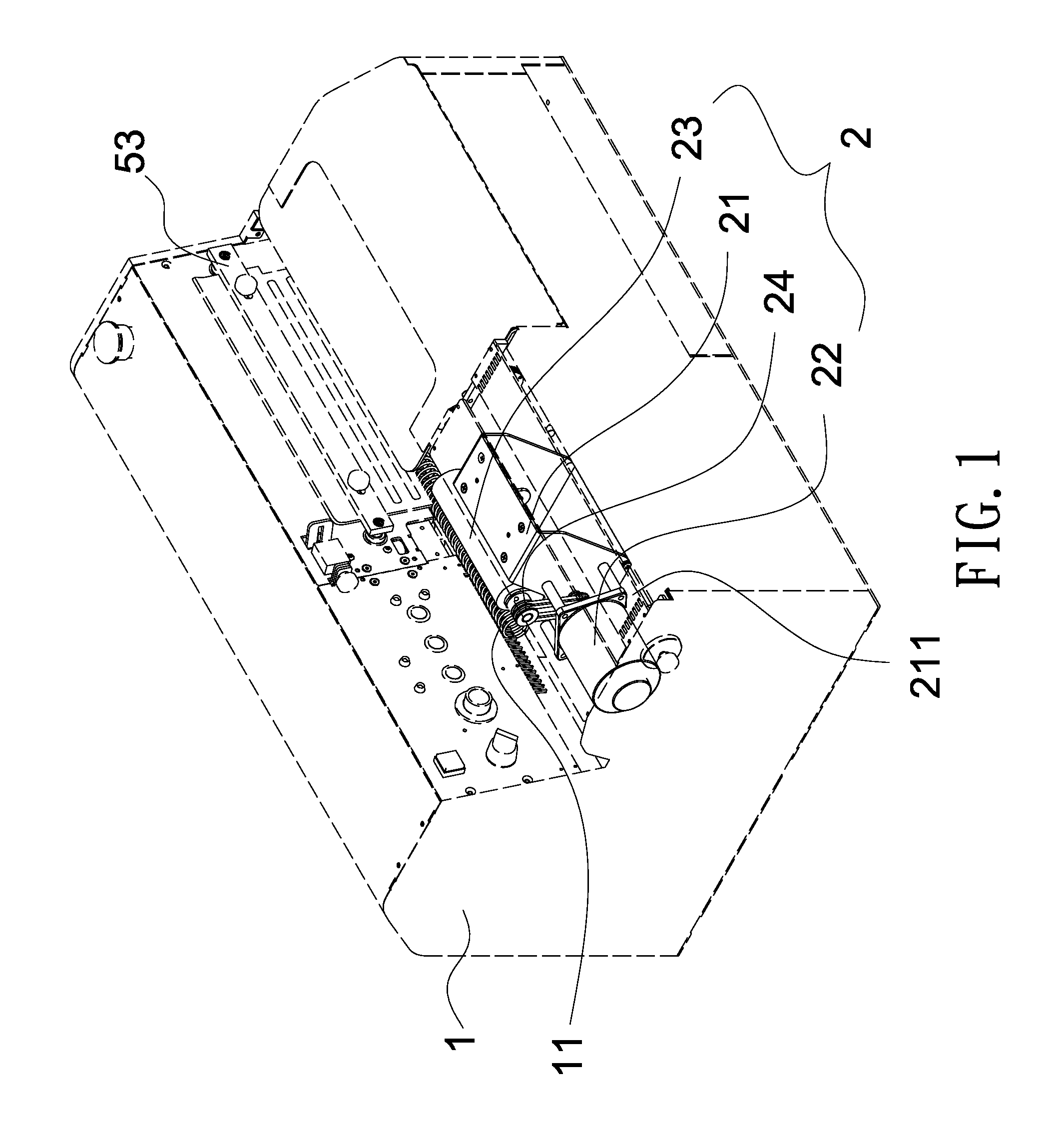
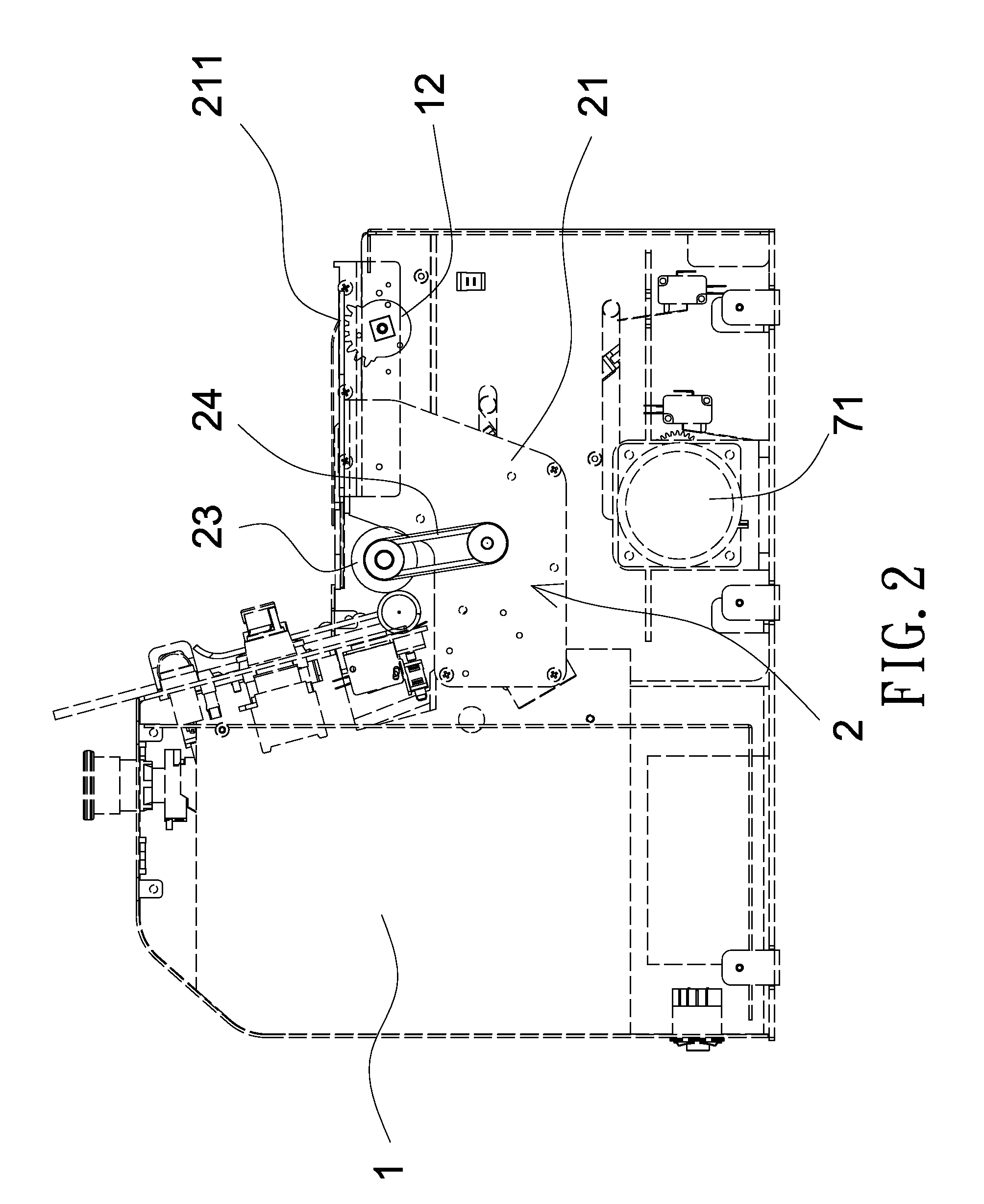
[0045]Referring to FIGS. 1-21, a preferred embodiment of the present invention provides a book coil binding machine, which comprises a housing 1, a conveying device 2, a coil guiding block 3, a coil sensor 4, a clamping device 5, a supporting apparatus 6 and a cutting apparatus 7.

[0046]Referring to FIGS. 1-3, the housing 1 is firmly disposed on a flat surface, e.g. the ground. The housing 1 has an inclined guiding comb tooth 11 and a limit gear 12 which is able to pivotally rotate without displacements which are located at the left side of the housing 1.

[0047]Referring to FIG. 4, the coil guiding block 3 is removably disposed on the housing 1 and at the end of the path of the inclined guiding comb tooth 11. The coil guiding block 3 is bullet-shaped and a spiral groove 31 is formed on the outer peripheral surface of the coil guiding block 3.

[0048]Referring to FIG. 5 and FIG. 5A, the coil sensor 4 is disposed on the housing 1 and located at the central position adjacent to the coil gu...


PUM


Abstract

A book coil binding machine includes a housing, a coil guiding block, a conveying device, a clamping device, a supporting apparatus and a cutting apparatus. The coil guiding block is removably disposed on the housing. The conveying device drives a coil moving forwards along the coil guiding block. The clamping device clamps the book in the book clamping space for the coil being guided into the holes of the book when the clamping device is at the clamping position. The clamping device releases the book when the clamping device is at the releasing position. The supporting apparatus is provided for the book in the book clamping space being abutted thereto when the supporting apparatus is at a supporting position, whereas the supporting apparatus is departed from the book when the supporting apparatus is at a loosening position. The cutting apparatus cuts off the two ends of the coil which are extended out of the book when the cutting apparatus is at a cutting position.

Description

BACKGROUND OF THE INVENTION[0001]1. Field of the Invention[0002]The present invention relates to a book binding instrument. More particularly, the present invention relates to a book coil binding machine.[0003]2. Description of the Prior Art[0004]It is well-known for books, in particular, the loose-leaf books, holes are perforated on a side of the books and equipped with the spiral coil for the convenience of page turning and paper tearing.[0005]Conventionally, in the procedures of equipping the coil into the books, the cutting for the coil is performed in advance according to the dimensions of the books. After the coil is cut with the predetermined length, the coil would be then manually passed through the holes of the books one by one. However, since the books are printed in large quantities, the manual operations must delay the binding procedures and be disadvantageous to mass production.[0006]Thus, in the market, there are machines which are able to bind the coils into the books...

Claims


Application Information

Patent Timeline
Patent Type & Authority Applications(United States)
IPC IPC(8): B42C13/00
CPCB42C13/00B42B5/123
Inventor CHIANG, CHOU-CHIH
Owner CHUNG SHEEN TECH
Why Eureka
Try Eureka