Device for encapsulating a component with plastics material

US20140093601A1Active Publication Date: 2014-04-03ROBERT BOSCH GMBH

Image

  • Device for encapsulating a component with plastics material
  • Device for encapsulating a component with plastics material
  • Device for encapsulating a component with plastics material

Examples


Embodiment Construction

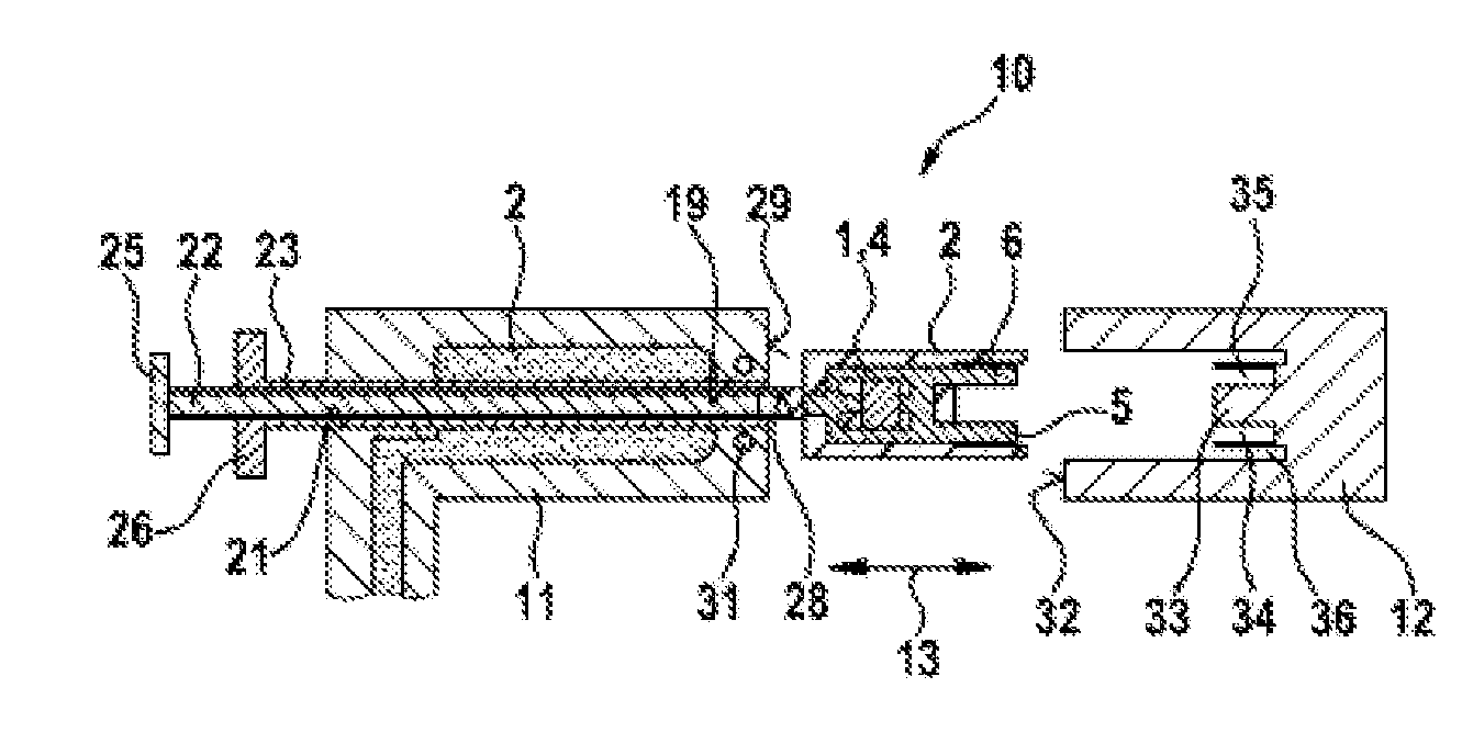
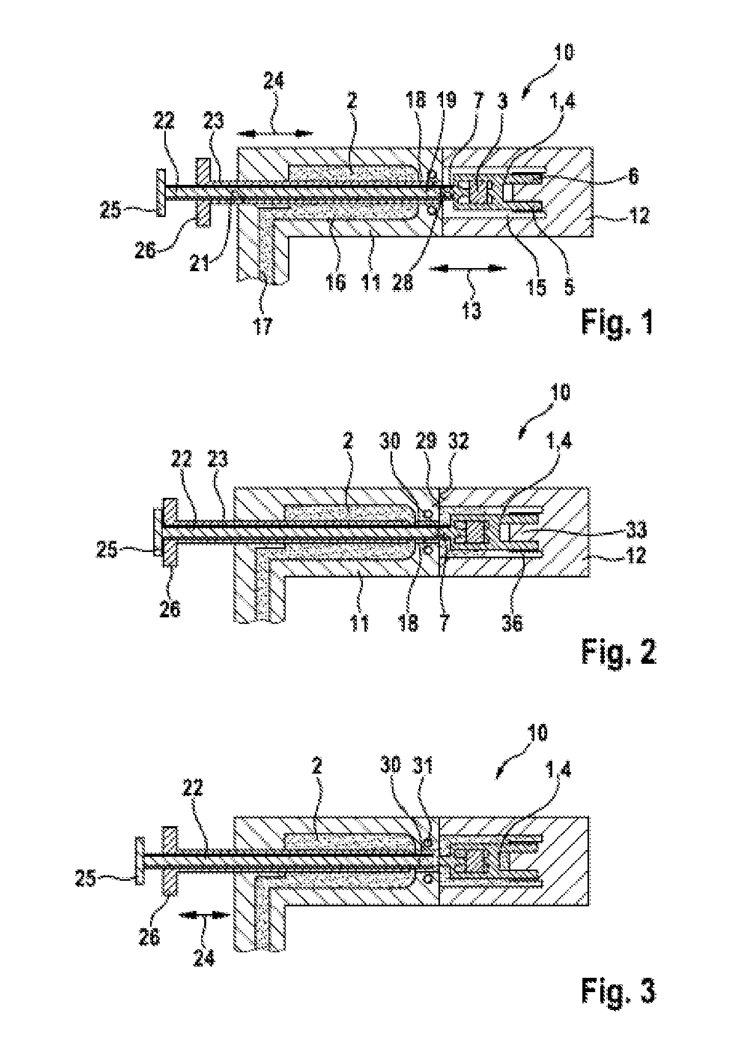
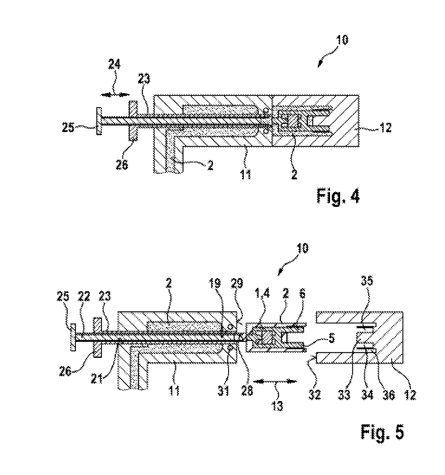
[0015]In FIGS. 1 to 5, a first device 10 according to the invention for encapsulating a component 1 with plastics material 2 is represented. The component 1 is, for example, but not in a restrictive sense, a sensor 4, which has an electronic circuit 3 and can by way of example be electrically contacted by means of two electrical terminal lugs 5, 6. It is intended here for the sensor 4 to be encapsulated with the plastics material 2 with the exception of in the region of the terminal lugs 5, 6.

[0016]The device 10 has two tool halves 11, 12, which are movable with respect to one another in the direction of the double-headed arrow 13 by means of a drive that is not represented. A fundamental distinction is drawn here between two positions of the two tool halves 11, 12: in one position, represented in FIG. 5, the sensor 4 can be introduced into the device 10 before the encapsulation and removed from the device 10 after the encapsulation, while in the closed position of the two tool halv...


PUM

PropertyMeasurementUnit
Flow rateaaaaaaaaaa
Diameteraaaaaaaaaa

Abstract

The invention relates to a device (10; 10a) for encapsulating a component (1) with plastic material (2), comprising at least two tool parts (11, 12), which in a closed arrangement for encapsulating the component (1) form a receptacle (15) for the component (1), an injection channel (30) for supplying the liquefied plastic material (2) to the region of the receptacle (15), and a single retaining element (22) for positioning the component (1) in the receptacle (15), wherein the retaining element (22) can be moved in a first position for positioning the component (1) in the receptacle (15) and in a second position for preferably completely encapsulating the component (1) with the plastic material (2). According to the invention, the retaining element (22) holds the component (1) in the region of the receptacle (15) by means of form positive and / or clamping engagement.

Description

BACKGROUND OF THE INVENTION[0001]The invention relates to a device for encapsulating a component with plastics material.[0002]Such a device is known from DE 10 2007 036 264 A1. The known device has a tool consisting of two tool halves, which are movable with respect to one another, and in the closed state form a receptacle for the encapsulation of a component. In one tool half there is formed a through-opening, in which a slide is arranged in a longitudinally movable manner, serving for positioning the component to be encapsulated. In the previously known document, the component to be encapsulated is an element of a permanent magnet, so that it can be positioned merely by being placed on the planar surface of the pin-shaped holding element consisting of metal. As soon as the component to be encapsulated is encapsulated in certain regions and the plastics material has set, the holding element can be retracted in its through-bore, after which the not yet encapsulated region of the com...

Claims


Application Information

Patent Timeline
03 Apr 2014
Publication
US20140093601A1
IPC
B29C45/14
CPC
B29C45/14065; B29C45/14073; B29C2045/14122; B29C45/14639
Inventors
KUNERT, PETER; OHL, CHRISTIAN