Plate-type reactor with in-situ injection

Active Publication Date: 2014-04-03
ARKEMA FRANCE SA
View PDF3 Cites 7 Cited by
  • Summary
  • Abstract
  • Description
  • Claims
  • Application Information

AI Technical Summary

Benefits of technology

The present invention is a fixed bed reactor that improves control of reaction temperature. It uses a plate reactor geometry with injection devices that pass through the plates for in situ injection of a substance. This allows better control over the chemical processes and faster regeneration of the catalyst. The invention also increases yield and productivity of the reactor by several percent. The invention reduces risks of explosion or runaway and limits down times of the reactor for regeneration.

Problems solved by technology

This geometry exhibits in particular the disadvantage of involving relatively complex and lengthy operations for charging and discharging catalyst which result in losses in productivity.
Furthermore, multitubular reactors exhibit a very high manufacturing cost but also a very high weight related to the masses of metals which it is necessary to use.
Another constraint on these reactors is related to their method of manufacture and transportation: they are limited in size as, manufactured and tested in a factory, they subsequently have to be transported to the site of final use.
All the above reactors exhibit the disadvantage of not making possible sufficient control / management of the temperature in the reactor, in the reaction phase and / or in the regeneration phase.

Method used


Image

  • Plate-type reactor with in-situ injection
  • Plate-type reactor with in-situ injection
  • Plate-type reactor with in-situ injection

Examples


Embodiment Construction

[0040]The invention is now described in more detail and without limitation in the description which follows.

General Description of the Reactor

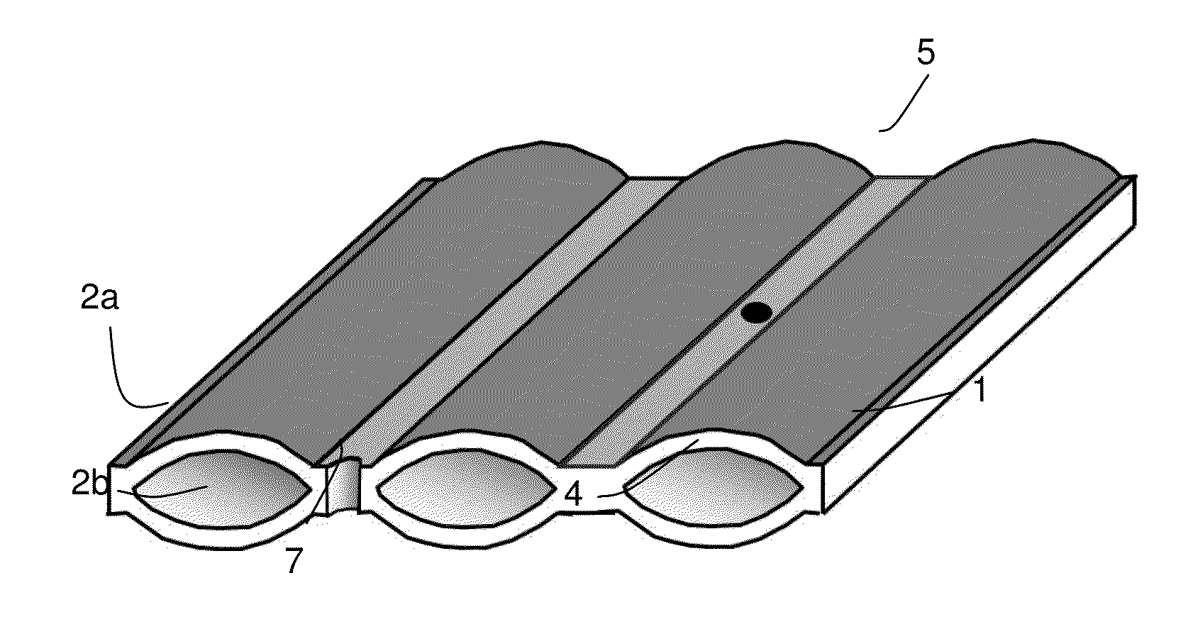
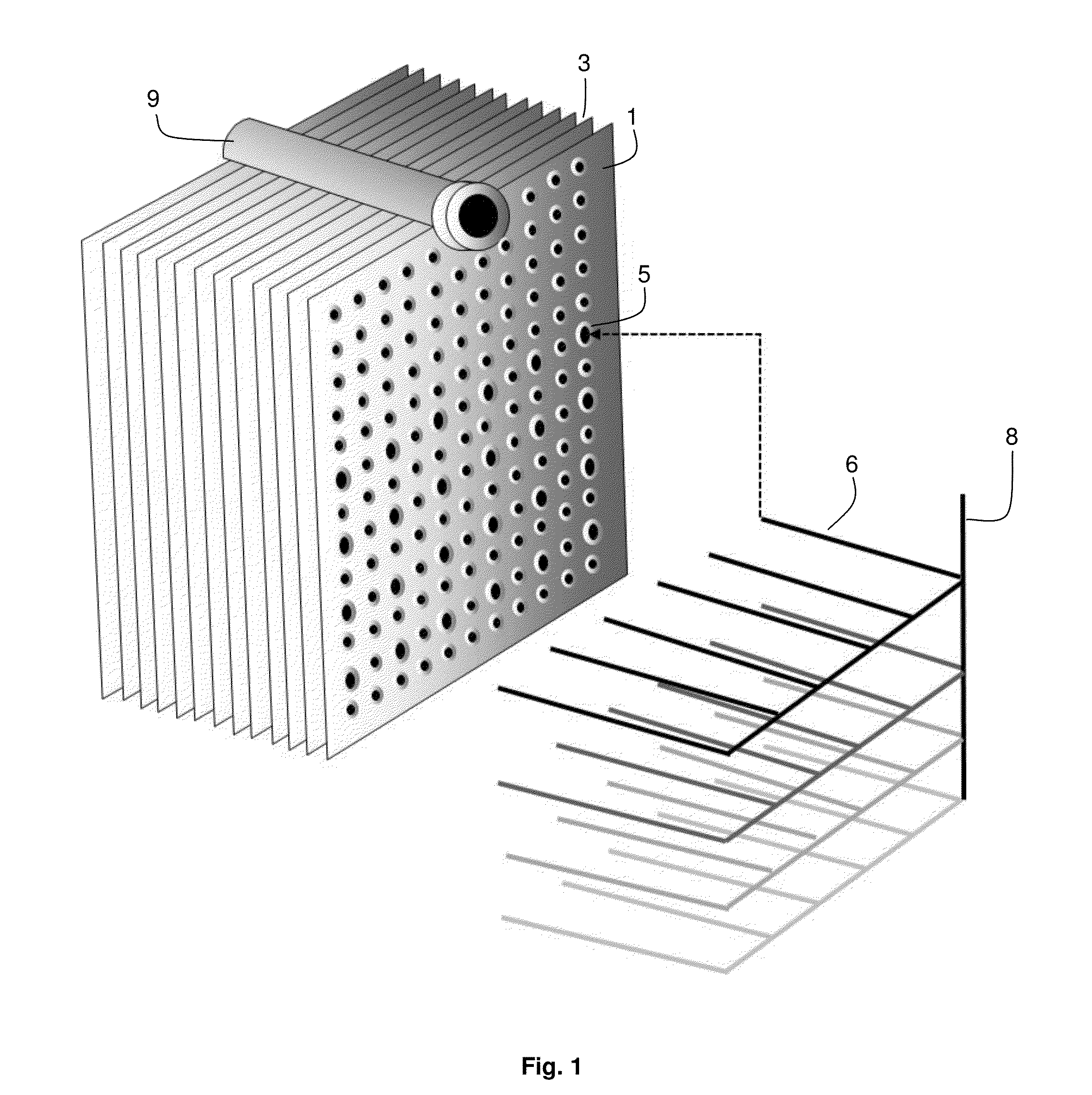
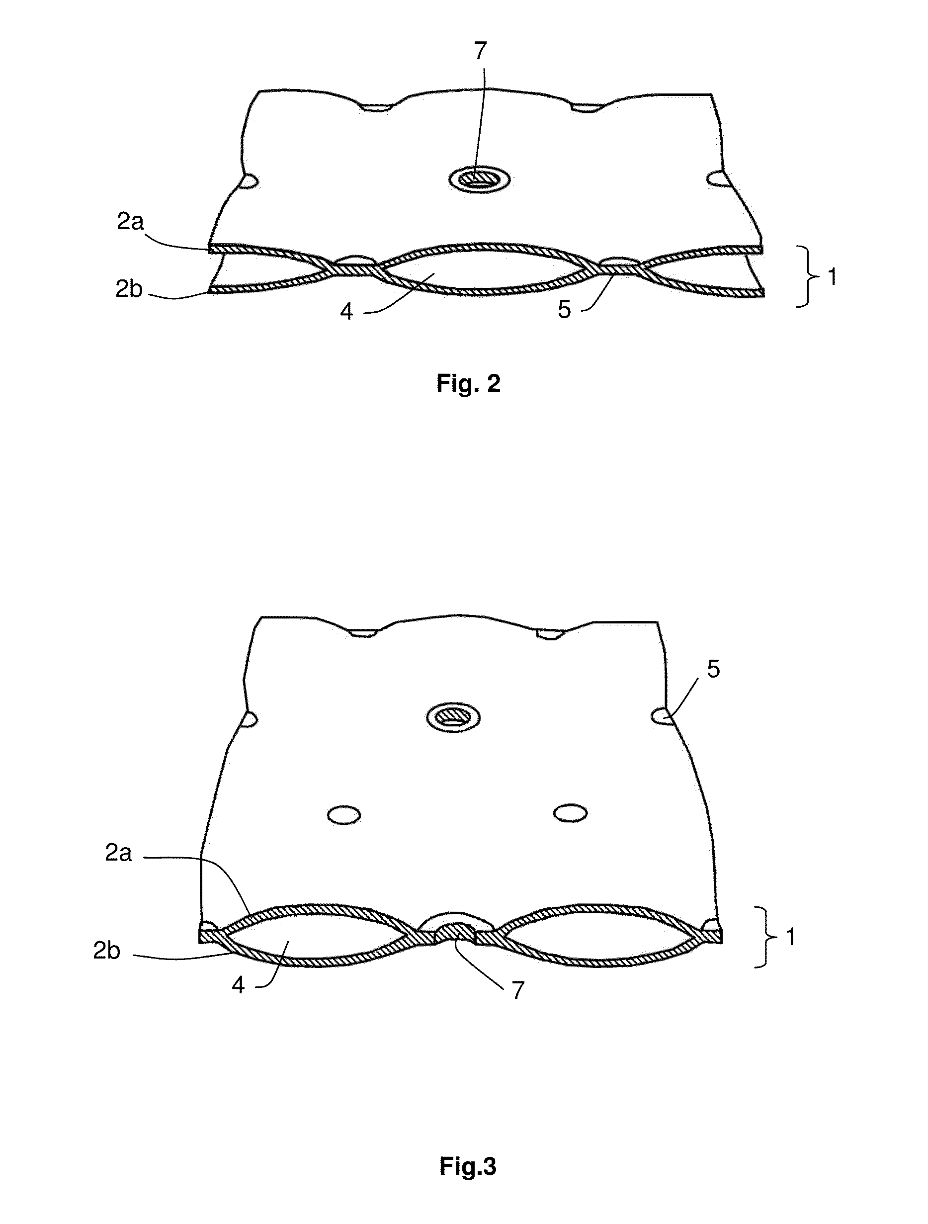
[0041]With reference mainly to FIGS. 1 and 4, generally, the reactor according to the invention comprises a chamber, which is advantageously essentially cylindrical with a circular section, inside which is positioned an assembly of heat-exchange plates 1 delimiting, between them, reaction compartments 3.

[0042]The reaction compartments 3 are advantageously filled with a catalyst appropriate for the reaction carried out, this catalyst preferably being in the form of solid particles (beads, grains or powder) or in the form of porous monolith or of blocks of porous monolith.

[0043]The reactor can operate according to at least two modes, namely a production mode, during which the targeted chemical reaction takes place in the reaction compartments; and a regeneration mode, during which the at least partially deactivated catalyst is regenerated.

[0044]...


PUM


Abstract

A chemical reactor including: a plurality of heat exchange plates which between them define reaction compartments, in which reactor each heat exchange plate includes two walls between them defining at least one heat exchange space, the respective walls being fixed together by joining regions, and the reactor also comprises at least one injection device for injecting substance into the reaction compartments, said substance-injection device passing through the heat-exchange plates in respective joining regions thereof. Also, a chemical reaction process that can be carried out in this reactor.

Description

[0001]The present invention relates to a chemical reactor exhibiting a geometry of plate type which makes possible the in situ injection of a substance, such as oxygen, into the reaction medium, optionally in multistaged fashion. The invention also relates to a chemical reaction process using said reactor.TECHNICAL BACKGROUND[0002]The use of chemical reactions, in particular involving heterogeneous catalysis, in fixed bed reactors is known. When these chemical reactions are highly endothermic or highly exothermic, control of the heat absorbed or emitted by the reaction presupposes that the reactor has available extensive heat-exchange surfaces.[0003]For example, a conventional geometry of fixed bed chemical reactors is the multitubular geometry. This geometry exhibits in particular the disadvantage of involving relatively complex and lengthy operations for charging and discharging catalyst which result in losses in productivity. Furthermore, multitubular reactors exhibit a very high...

Claims


Application Information

Patent Timeline
IPC IPC(8): B01J19/24
CPCB01J19/249B01J2219/2453B01J2219/2455B01J2219/2459B01J2219/246B01J2219/2462B01J2219/247B01J2219/2481F28F9/027F28D9/0043F28D2021/0022C07D307/60C07D307/89C07C41/01C07C45/29C07C45/35C07C45/512C07C51/347
Inventor DUBOIS, JEAN-LUC
Owner ARKEMA FRANCE SA
Why Eureka
Try Eureka